P/N 960-100189RA_Rev. A {EDP #148850} © 2009, Japan CashMachine Co., Limited
Dissassembly/Reassembly VEGA™ Series BankNote Validator Section 4
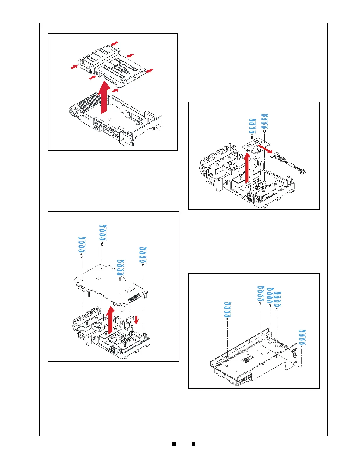
15. Remove the four (4) mounting screws (See Figure
4-10 a
1
through a
4
) retaining the Main CPU
Board in place (See Figure 4-10 b).
Carefully lift the Main CPU Board up,
and unplug
the single Circuit Board Connector from the
Board (See Figure 4-10 c); then lift the CPU
Board up and off the Upper Transport Assembly
(See Figure 4-10 d).
Upper Sensor Board Removal
To remove the VEGA Unit’s Upper Sensor Board,
proceed as follows:
1. Remove the two (2) mounting screws (See Figure
4-11 a
1
& a
2
) securing the Upper Sensor Board in
place (See Figure 4-11 b), and unplug the single
Circuit Board Connector (See Figure 4-11 c)
located on the Upper Sensor
Board.
2. Lift the Sensor Board up and off the Upper Trans-
port Assembly (See Figure 4-11 d).
Sub-Circuit Board Removal
To remove the VEGA Unit’s Sub-Circuit Board,
proceed as follows:
1. Remove the five (5) Sub-Circuit Circuit Board
Mounting Screws (See Figure 4-12 a
1
through a
5
)
from the back side of the removed Lower Trans-
port Assembly.
2. Unplug the single Sub-CircuitBoard Connector
(See Figure 4-13 a) from the Lower Transport
Assembly (See Figure 4-13 b).
Figure 4-9 Upper Transport Assembly Removal
Figure 4-10 Main CPU Board Removal
Figure 4-11 Upper Sensor Board Removal
Figure 4-12 Base Unit Carrier Removal (Part 1)

 Loading...


