P/N 960-100189RA_Rev. A {EDP #148850} © 2009, Japan CashMachine Co., Limited
Dissassembly/Reassembly VEGA™ Series BankNote Validator Section 4
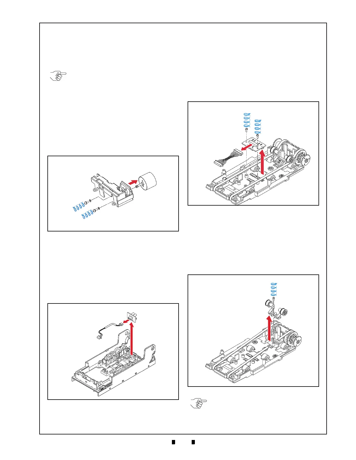
2. Remove the three (3) mounting screws
(See Figure 4-16 d
1
to d
3
) retaining the Stacker
Gear Box Sub-assembly (See Figure 4-16 e) to
the Lower Transport Assembly, and lift the
S
tacker Gear Box Sub-assembly up and off the
Lower Transport Assembly.
3. Remove the two (2) mounting screws (See Figure
4-17 a
1
& a
2
) retaining the Stacker Motor to its
Sub-assembly (See Figure 4-17 b) and remove the
Stacker Motor out of the
Stacker Gear Box Sub-
assembly (See Figure 4-17 c).
Sub-Sensor Board Removal
To remove the VEGA Unit’s Sub-Sensor Circuit
Board, proceed as follows:
1. Unplug the single Circuit Board Connector
(See Figure 4-18 a) attached to the Sub-Sensor
Board (See Figure 4-18 a).
2. Lift the Sub-Sensor Circuit Board
and off the
Lower Transport Assembly (See Figure 4-18 b).
Lower Sensor Board Removal
To remove the VEGA Unit’s Lower Sensor Circuit
Board, proceed as follows:
1. Remove the two (2) mounting screws (See Figure
4-19 a
1
& a
2
) retaining the Lower Sensor Board
(See Figure 4-19 b) to the Base Carrier Unit
(See Figure 4-19 c); then unplug the single
Circuit Board Connector (See Figure 4-19 d).
2. Lift the Lower Sensor Board up and off the Base
Carr
ier Unit.
Transport Belt Removal
To remove the VEGA Unit’s Transport Belts,
proceed as follows:
1. Remove the single mounting screw (See Figure 4-
20 a) retaining the Tension Pulley Assembly in
place (See Figure 4-20 b). Take the Tension
Pulley Unit off the Carrier Base Unit (See Figure
4-20 c).
NOTE: Both Gear Box Sub-assemblies
are identical! When reassembling the
Gear Box Sub-assemblies, identify the
gears by the labels located on each Box.
The Yellow label is located on the Stacker
Motor Housing (See Figure 4-16 g), and
the White label is located on the Feed
Motor Housing (See Figure 4-16 f).
Figure 4-17 Stacker & Feed Motor Removal
Figure 4-18 Sub-Sensor Board Removal
Figure 4-19 Lower Sensor Board Removal
Figure 4-20 Tension Pulley Unit Removal
NOTE: Be careful that the two (2) left and
right side Tension Pulleys do not fall out of
the Assembly (See Figure 4-20 d) when
removing the Tension Pulley Unit.

 Loading...


