P/N 960-100189RA_Rev. A {EDP #148850} © 2009, Japan CashMachine Co., Limited
Section 1 VEGA™ Series BankNote Validator General Information
Model/Type Number Specifications
Precautions
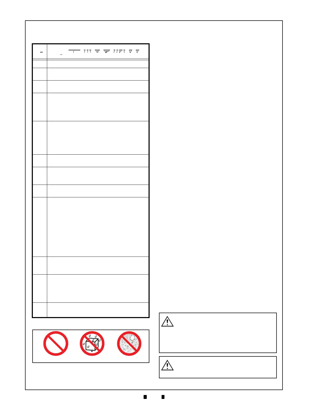
The Figure 1-2 symbols are defined as follows:
1. (Type 1) Do not insert a torn, folded, or wet Ban-
knotes, as this action may cause a Banknote jam
in
side the unit.
2. (T
ype 2) Do not expose the unit to water. The
unit contains several precision electronic devices
which can be damaged into the unit.
3. (T
ype 3) Do not install the unit into a dusty envi-
ronment. Dust may affect and degrade a Sensor’s
performa
nce.
I
NSTALLATION
P
RECAUTIONS
The following precautions should be observed
when handling and installing a VEGA Unit:
1. This equipment is not fully warranted for outdoor
use. Be sure the Host Machine contains enough
protection to avoid wet or dusty conditions when
installing it in both open-air and indoor spaces.
2. Be sure the Host Machine is designed with
careful consideration for retrieving
a Banknote
and/or clearing a Banknote jam.
3. Be careful not to use exc
essive outside pressure
on the Mounting Plate when removing the Cash
Box from the Unit.
4. Avoid exposing the Banknote Insertion
Slot to
direct Sunlight and/or Incandescent Lamp ill-
umination having a Gradient Angle of 15
Degrees or more, and an illumination index of
3000 Lux or less. Insure that the Host Machine is
also designed to avoid exposing the Banknote
Insertion Slot to direct Sunlight or incandescent
light contact.
5. Do not allow the Validator
to endure a range of
temperature and humidity beyond the environ-
mental limits specified (See “Environmental
Specifications” on page 1-6 of this Section).
6. Do not use the Validator when placed in severe
T
emperature changing environments.
7. Do not use the Validator in a place having air
born evaporate
d or sporadic chemicals.
8. Clean and maintain the Validator regularly when
lo
cated in an excessively smoke filled environ-
ment.
U
SER
P
RECAUTIONS
The following User precautions should be
observed when installing, operating and servicing
the Unit:
1. When closing the Upper portion of the Transport
path or the Course Path Reversing Guide Cover,
ensure that it clicks firmly into place.
Table 1-1: Model Number Specifications
N
o
Model: VEGA - * * * - *** - **** - * * ** * - ** - **
N
o
(1) (2,3,4) (5) (6) (7,8,9,10)(11) (12)
(1) Product Series Name
(2) CPU Board Type
1. Standard
(3) Durability
0 = Standard
(4) SUB Board
0 = 12V DC Power (NO Magnetic Sensor)
1 = 12V DC Power / Magnetic Sensor
2 = 24V DC Power / NO Magnetic Sensor
3 = 24V DC Power / Magnetic Sensor
(5) Stacker Type
SH = Downward horizontal stacking
SU = Upward vertical stacking
SD = Downward vertical stacking
SUR = Upward vertical stacking (Backside removal)
SDR = Downward vertical stacking (Backside removal)
(6) Country Code
Refer to Specific County’s “Software Information Sheet”
(7) Cash Box
3 = Standard Box
A = Large Box
(8) Lock
0 =Thumb Lock
(9) Bezel
01 = SH 68mm (EUR)
02 = SH 76mm (GBR/SCO/NIRL)
03 = SH 71mm (RUS)
04 = SH 77mm (JPN)
05 = SH 67mm (USA)
N1 = SU/SD 68mm (EUR)
N2 = SU/SD 76mm (GBR/SCO/NIRL)
D1 = SU/SD 67mm (USA)
D2 = SU/SD 71mm (RUS)
D3 = SU/SD 68mm (EUR)
(10) Box Access
F = Front Access
B = Rear Access
(11) Option
00 = NO Option
01 = Frame Key
02 = Bezel Protector
03 = Frame Key + Bezel Protector
(12) Interface
I4 = 4 Types
Type 1Type 2Type 3
Figure 1-2 Precautionary Symbols
Caution: Turn the VEGA’s Power OFF
when opening the Upper or Lower
Guide; otherwise, the Rollers may
begin operating and personal injury to
fingers may occur buy getting them
pulled into the Unit.
Caution: Be careful to avoid personal
injury to your fingers when closing the
Upper Guide Section.

 Loading...


