P/N 960-100189RA_Rev. A {EDP #148850} © 2009, Japan CashMachine Co., Limited
Installation/Operation VEGA™ Series BankNote Validator Section 2
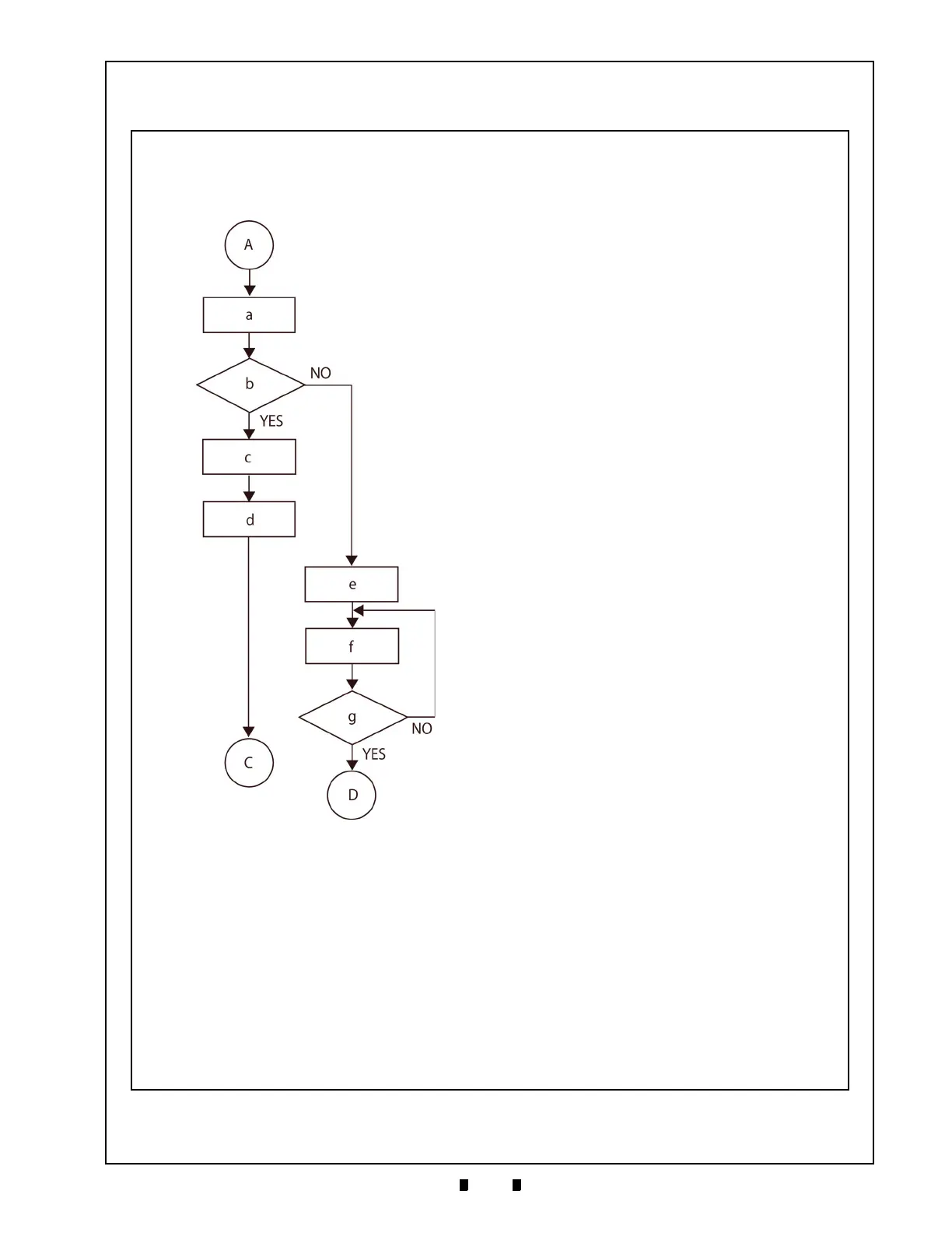
Operational Flowchart (Continued 1)
Figure 2-18 depicts part two of a typical VEGA Banknote stacking flow process.
Figure 2-18 VEGA Banknote Validator Operational Flowchart (Part 2 Stack)
b) Complete Banknote Transportation?
a) Banknote Transportation to Stacker
c) Vend Signal Output
d) Complete Stacking Process
e) Stop Banknote Movement
f) LED Display Blinks Red Light
g) Remove Banknote from the Transport Path?
A) Begin Stacking
D) Return to Initializing (See Figure 2-17 on page
2-8)
C) Return to Stand-by (See Figure 2-17 on page
2-8)

 Loading...


