P/N 960-100189RA_Rev. A {EDP #148850} © 2009, Japan CashMachine Co., Limited
Troubleshooting VEGA™ SeriesBankNote Validator Appendix A
Red
3
(300)
White
3
(300)
Feed Motor Low
S
peed Problem
While operating the Feed Motor, no pulse input exist
s greater than the rated value.
[Solution] Check that the following parts are properly assembled and/or harness connected.
Feed Motor: SUB Board CN2 & CN3, CPU Board CN4.
If the error is not resolved, change the above related part or parts.
Red
3
(300)
White
5
(300)
Feed Motor High
S
peed Problem
While operating the Feed Motor, no pulse input exist
s greater than the rated value.
[Solution] Check that the following parts are properly assembled and/or harness connected.
Feed Motor: SUB Board CN2 & CN3, CPU Board CN4.
If the error is not resolved, change the above related part or parts.
Red
3
(300)
White
7
(300)
Feed Motor
L
ock-up Problem
While operating the Feed Motor, no pulse input exist
s greater than the rated value. (This error
occurs while initializing, or when a Banknote is at a transport position where it can not be
returned.)
[Solution] Check that the following parts are properly assembled and/or harness connected.
Feed Motor: SUB Board CN2 & CN3, CPU Board CN4.
If the error is not resolved, change the above related part or parts.
Red
3
(300)
Purple
5
(300)
Stacker Motor
L
ock-up Problem
While operating the Stack Motor, no pulse input exists greater than the rated value.
[Solution] Check that the following parts are properly assembled and/or harness connected.
Stack Motor: SUB Board CN4 & CN3, CPU Board CN4.
If the error is not resolved, change the above related part or parts.
Red
3
(300)
Purple
7
(300)
Stacker Motor
G
ear Problem
The Pusher Mechanism stays in its home position while the Stacker Motor is operating.
[Solution] Check that the following parts are properly assembled and/or harness connected,
a
nd clean all of the Sensors.
Stack Motor: SUB Board CN4 & CN3, CPU Board CN4,
Pusher Mechanism & Home Position
Sensor: SUB Board LED7 & PT2 &CN8, CPU Board CN8.
If the error is not resolved, change the above related part or parts.
Red
3
(300)
Blue
2
(300)
Banknote
T
ransportation
Slips
An abnormal Banknote transportation error is d
etected when transporting or rejecting
Banknotes. The Transportation Slip Sensors do not detect continuous Banknotes being
transported according to the rated value.
[Solution] Check that the following parts are properly assembled and/or harness connected,
a
nd clean all of the Sensors.
Feed Motor: SUB Board CN2 & CN3, CPU Board CN4.
Stack-in Sensor: SUB Sensor Board (Upper) LED2, PS2
& CN1, SUB Board CN6 & CN8, CPU
Board CN7.
Cash Box Sensor: SUB Sensor Board (Upper) LED3, P
S3 & CN1, SUB Board CN6 & CN8, CPU
Board CN7.
Storage Flap Sensor: CPU Board F-SENS1.
Escrow Sensor: CPU Board LED
1 & P-SENS1.
Validation Sensor: Sensor Board (Upper) & Sensor Board (Lowe
r), LED1 & LED3 & PT1, LED2
& LED4 & PT2, LED5 & PT3.
If the error is not resolved, change the above related part or parts.
Red
3
(300)
Blue
3
(300)
Transportation
T
imes out
An abnormal Banknote transportation error is d
etected when transporting or rejecting
Banknotes. The Transportation Locks-up or is running too slow. Sensors detect continuous
Banknotes being transported according to the rated value.
[Solution] Check that the following parts are properly assembled and/or harness connected,
a
nd clean all of the Sensors.
Feed Motor: SUB Board CN2 & CN3, CPU Board CN4.
Stack-in Sensor: SUB Sensor Board (Uppe
r) LED2&PS2&CN1, SUB Board CN6 & CN8, CPU
Board CN7.
Cash Box Sensor: SUB Sensor Board (Upper) LED3 &
PS3 & CN1, SUB Board CN6 & CN8,
CPU Board CN7.
Storage Flap Sensor: CPU Board F-SENS1.
Escrow Sensor: CPU Board LED
1&P-SENS1.
Validation Sensor: Sensor Board (Upper) & Sensor Board (Lowe
r), LED1 & LED3 & PT1, LED2
& LED4 & PT2, LED5 & PT3.
If the error is not resolved, change the above related part or parts.
Red
3
(300)
Red
3
(300)
Abnormal
T
iming Response
(Transport,
Reject
, other)
Sensors detect Banknotes remain in path or
none exist during abnormal timing.
[Solution] Check that the following parts are properly assembled and/or harness connected,
a
nd clean all of the Sensors.
Stack-in Sensor: SUB Sensor Board Upper LED2
& PS2 & CN1, SUB Board CN6 & CN8, CPU
Board CN7.
Box Sensor: SUB Sensor Board (Upper) LED3 &
PS3 & CN1, SUB Board CN6 & CN8, CPU
Board CN7.
Store Flap Sensor: CPU Board F-SENS 1.
Escrow Sensor: CPU Board LED
1 & P-SENS1.
RC Flap Sensor: CPU Board F-SENS2.
Side Sensor: CPU Board SIDE-LED & SIDE
Pusher Mechanism Home Position Sensor: SUB Board LED7
& PT2 & CN8, CPU Board CN8
Validation Sensor: Sensor Board (Upper) & Sensor Board (Lower) LED1 & LED3 & PT1, LED2
& LED 4& PT2, LED5 & PT3.
If the error is not resolved, change the above related part or parts.
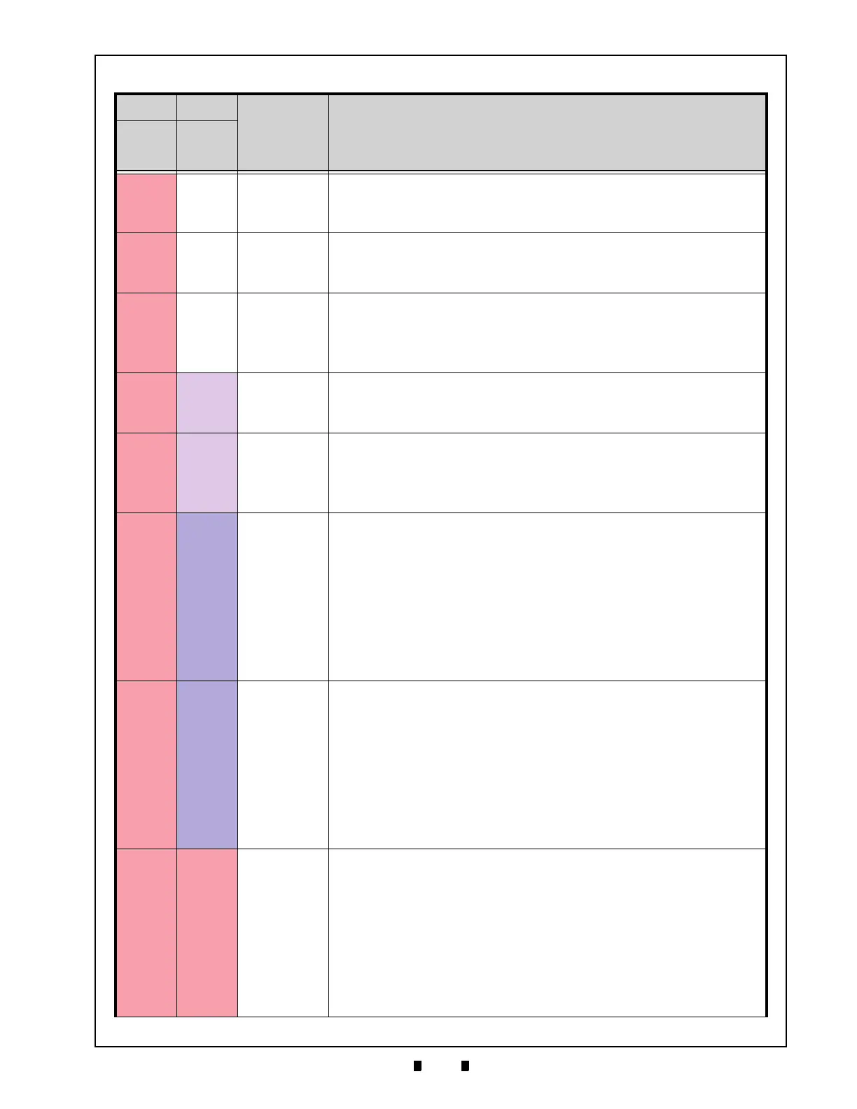
Table A-2 Error Codes (Continued)
on-line off-line
Error Causes and Solutions
Color
Flashes
(msec)
Color
Flashes
(msec)

 Loading...


