1 Removethefrontpanel(Figure5)
2 NoteandrecordthecolorandlocationofeachwireonthethermocoupleterminalslocatedontheMain
PCBoardRemovebothwires
3 Removethecalibrationjackconnector(J1)fromtheMainPCBoardbypullingstraightup
4 Removefiveelectricalconnectors(BLACK,ORANGE,YELLOW,WHITE,GREEN)fromtheMainPCBoardby
pullingstraightupontheconnectorDONOTPULLONTHEWIRES
5 RemovethenutsandlockwashersthatholdtheMainPCBoardtothefrontpanelandliftstraightupto
removeboard
6 Aligntheholesinthenewboardwiththestandoffsonthefrontpanel,reinstallthefastenersandscrews
7 Reconnecttheelectricalconnectorsasfollows:
Blackwiretoterminalmarked“H”-E5
Orangewiretoterminalmarked“GATE”-E4
Yellowwiretoterminalmarked“LOAD”-E3
Whitewiretoterminalmarked“N”-E2
Greenwiretogroundterminal-E1
8 ReconnectcalibrationjackconnectorThegreenwireontheconnectorisclosesttothebottomedgeofthe
frontpanel
9 Reconnectthetwothermocouplewirestothethermocoupleterminalsobservingthecolorcodingnotedin
Step2Ifthermocouplewiresarereversed,5minutesafterheatingprogramisstarted,"Er5"willappear
ontheMainDisplay
10Replacethefrontpanel
FIELD SERVICE
REPLACEMENT OF THE MAIN PC BOARD
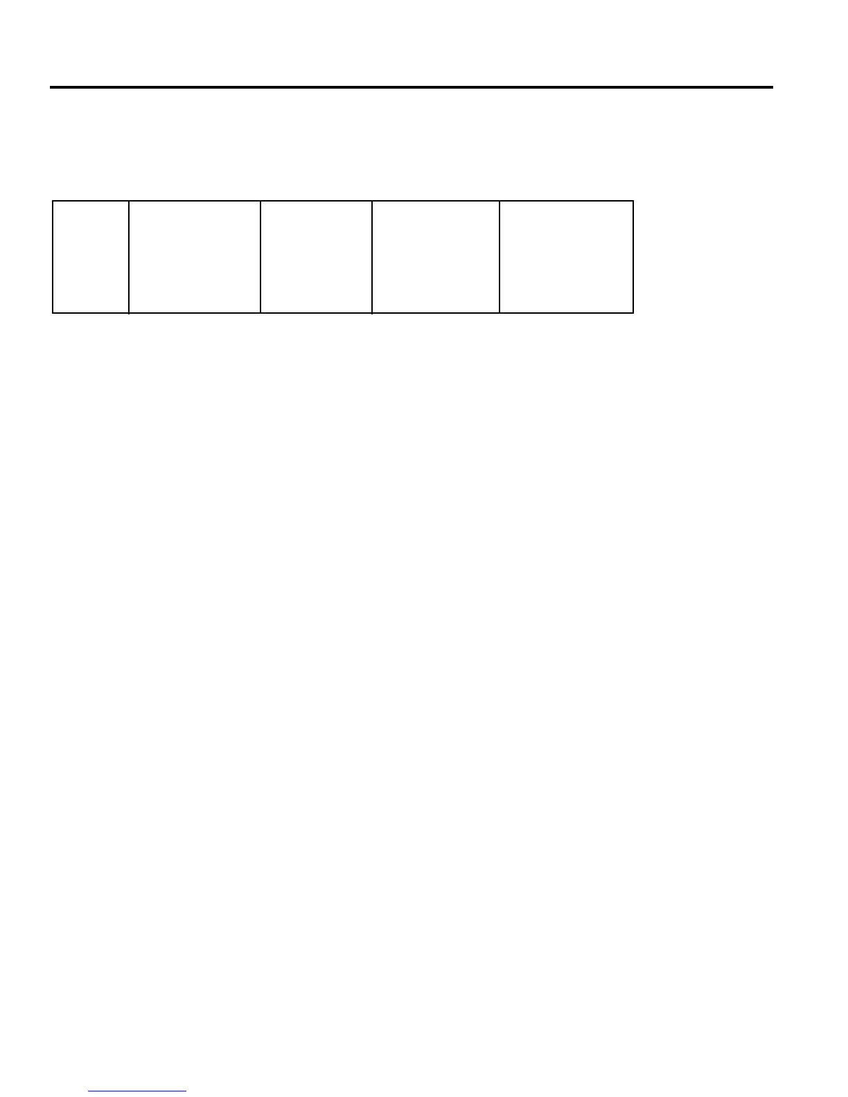
REPLACEMENTPARTNUMBERS
23
100V 115V 220/230V 240V
M-30 15500-031 15500-041 15500-053 15500-056
L-30 15500-531 15500-541 15500-553 15500-556
 Loading...