Two controls which are used in conjunction to set the digital readout to an
appropriate number when a calibration standard is aspirated.
A five position control which will select the appropriate optical filter for the
element being determined.
NOTE: For the PFP7/C positions 3 and 4 will normally be blank
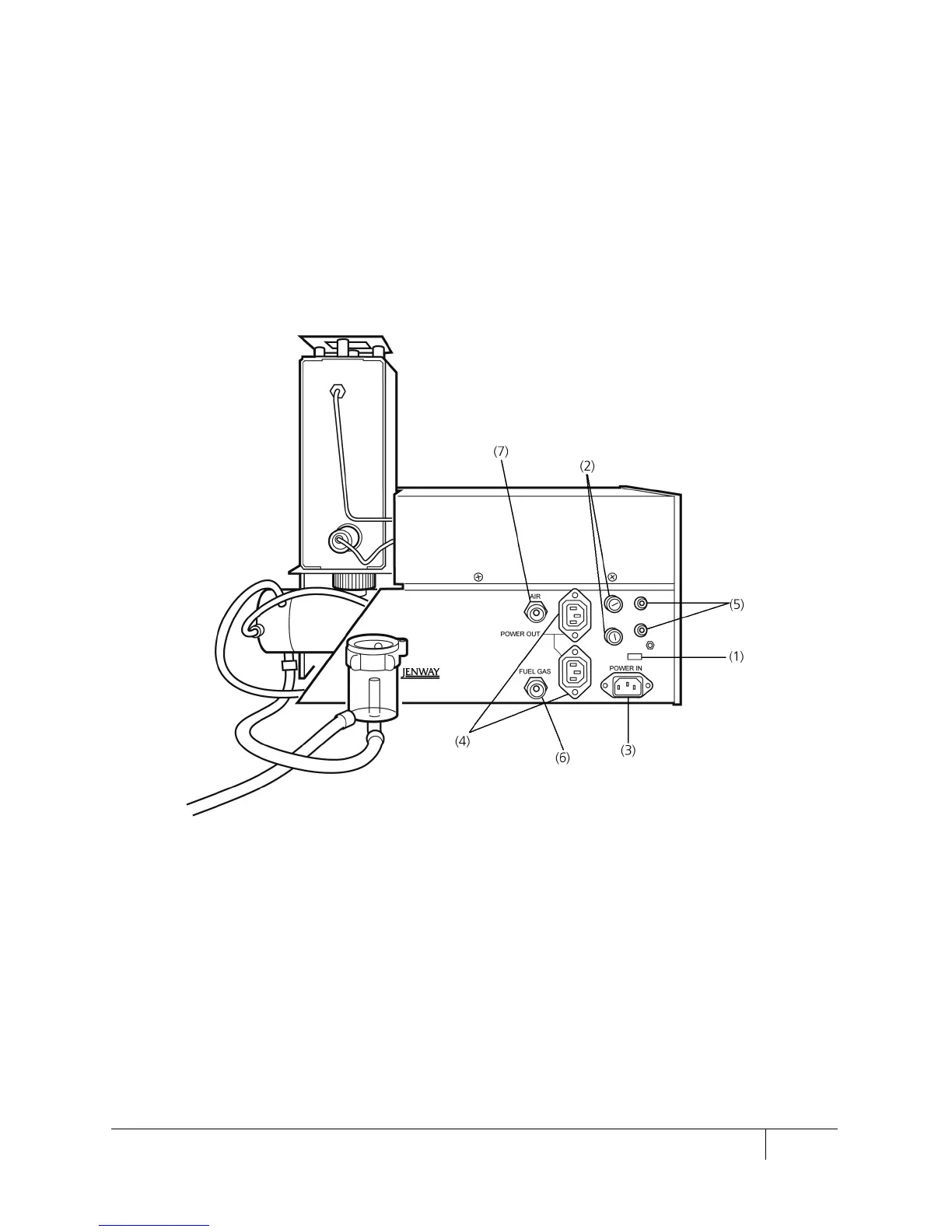
4.1.2 Rear panel controls
Figure 4.1.2.1: Rear panel
A two-position switch marked 230 and 115. These positions allow
operation from the voltage supplies 190
125 volts
respectively at either 50 or 60Hz.
WARNING: when adjusting the operating voltage it may be
necessary to change the
top fuse as indicated on the rear panel.
Please note that the unit is set to the required voltage in the factory
depending on the part code ordered.
 Loading...