Section 4
Operation
4.1 Front and rear panel controls
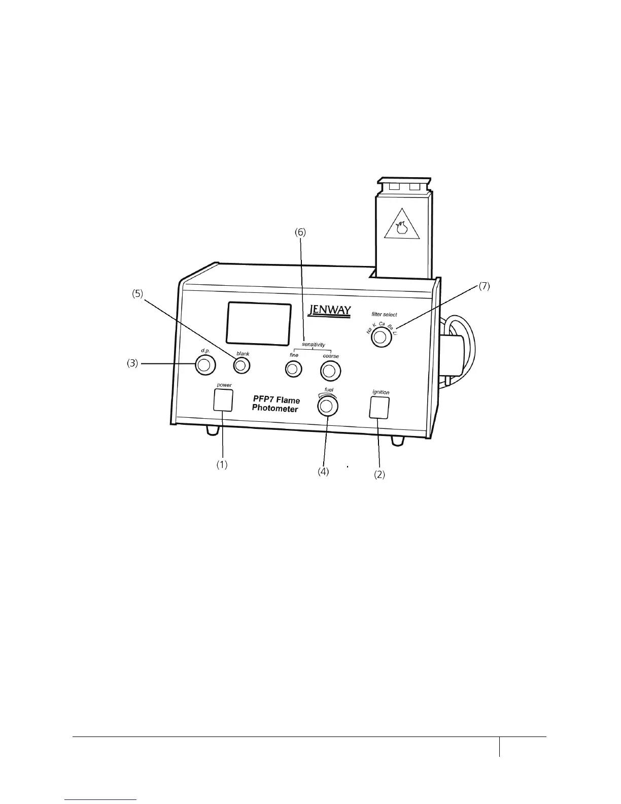
4.1.1 Front panel controls
Figure 4.1.1.1: Front panel
A two-position rocker switch which controls the AC supply of the instrument.
Any accessories connected to the auxiliary
POWER OUT sockets on the rear
panel are also controlled by the front panel power switch.
A spring loaded switch which, when depressed, will cause an electrical discharge
between the ignition electrode and the burner unit, thereby causing fuel
ignition.
This dial controls the position of the decimal point on the digital readout.
A fine needle valve that controls the flow of fuel and enables optimum flame
conditions to be set.
This dial control sets the zero point when a blank standard is aspirated.
 Loading...