This document is an instruction manual for the JEM-1200EX Electron Microscope, along with several attachments.
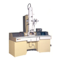
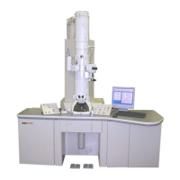
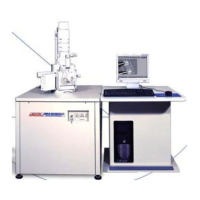
JEM-1200EX Electron Microscope
The JEM-1200EX is a high-resolution electron microscope designed for both combined electron microscopy and analytical electron microscopy. When used with scanning and analytical attachments, it provides comprehensive information about the specimen. It features a dry pumping system and a minimum electron dose system to improve the specimen environment. The optical system minimizes image rotation, field of view curtailment, and off-axial aberration. Keyboard operation allows free control of the optical system, storage and recall of specific conditions, CRT display of operating data (with film printout capability), and user comments. Axial alignment is simplified with step-by-step CRT guidance and automatic lens excitation settings.
Technical Specifications:
- Guaranteed Resolution: 0.14 nm (lattice), 0.3 nm (point to point)
- Accelerating Voltage: 40, 60, 80, 100, 120 kV
- Magnification (Digital Display, Film Printout):
- Standard magnification mode: 1,200X to 1,000,000X in 30 steps
- Selected area magnification mode: 4,000X to 500,000X in 22 steps
- Low magnification mode (LOW MAG): 50X to 1,000X in 14 steps
- Electron Diffraction Camera Length (Digital Display, Film Printout):
- Selected area electron diffraction: 100 to 2,500 mm in 15 steps
- High dispersion diffraction: 4 to 80 m in 14 steps
- High resolution diffraction: 337 mm (EM-AD high resolution diffraction stage: optional)
- Electron Gun (Cool-Beam Type):
- Filament: Precentered hairpin type tungsten filament, DC heating
- Bias: Self-bias, continuously variable
- Alignment: Electromagnetic 2-stage interlocking system
- Anode Chamber Airlock Mechanism and Electron Gun Lift: Built-in, pneumatic control
- Condenser Lens (Electromagnetic, Double Condenser Type):
- Aperture: 200, 300, 400 µm in diameter (click-stop changeover)
- Stigmator: Electromagnetic type, complete with centering device
- Alignment: Electromagnetic 2-stage interlocking system
- Beam Tilting Angle: Max. 6° in all directions
- Image Forming Lens System: Rotation-free, electromagnetic 6-stage system (objective lens, OM lens, 1st, 2nd and 3rd intermediate lenses, projector lens)
- Apertures (Molybdenum Film):
- Objective lens apertures: 20, 50 and 80 µm in diameter (click-stop changeover)
- Field limiting apertures: 20, 100 and 300 µm in diameter (click-stop changeover)
- Stigmator: Electromagnetic type, complete with centering device; two circuits each for low magnification and standard magnification
- Specimen Stage:
- Specimen Exchange: Airlock mechanism
- Loading Capacity: Two specimens
- Specimen Anticontamination Device: Optional (EM-ACD10)
- Specimen Movement Range: X and Y directions: ±1 mm; Z direction: ±0.5 mm
- Specimen Tilt Angle: ±25° (X tilt)
- High Resolution Diffraction Chamber: Choice of three types (EM-AD, EM-AHC, EM-ACC) – option extras
- Viewing Chamber:
- Viewing Window: 270 mm X 170 mm, 90 mm X 80 mm (2)
- Fluorescent Screens: 160 mm and 20 mm in diameter
- Binoculars (10X): Built-in
- Beam Stopper: Optional (EM-BS10)
- Camera Chamber:
- Film Standard Size: 65 mm X 90 mm
- Large Size: 80.9 mm X 99.6 mm (available to order)
- Loading Capacity: Up to 50
- Feeding: Fully automatic (single film feeding also possible)
- Exchange Mechanism: Airlock type
- Exposure: Automatic exposure (manual exposure also possible)
- Data Recording: Film number, magnification/camera length, accelerating voltage, micron bar and calibrated length, and characters (keyboard entry)
- Vacuum System:
- Vacuum Pumps: Oil rotary pump and two turbomolecular pumps, sputter-ion pump and oil diffusion pump
- Ultimate Pressure: 10⁻⁵ Pa (specimen chamber)
- Vacuum Gauges: Penning and Pirani gauges
- Vacuum Valves: Automatically controlled pneumatic and solenoid valves
- Installation Requirements:
- Power Supply: Single phase, 200/220/240V, 50/60 Hz, 5.5 kVA
- Grounding Terminal: 100 Ω or less, 1
- Cooling Water: Flow rate: 4 to 7 ℓ/min; Pressure: 0.1 to 0.4 MPa; Temperature: 15 to 20°C; Faucet: 14 mm O.D. (for 1/2" hose), 1
- Installation Room: Floor space: 2,800 mm (width) X 3,000 mm (depth) or more; Ceiling height: 2,500 mm or more; Doorway: Width: 800 mm or more, Height: 1,800 mm or more; Room temperature: 20 ± 5°C; Humidity: Below 80%; Tolerable external magnetic fields: Less than 0.1 µT; Floor strength: Better than 3.5 kPa; Compressed air: 0.35 to 0.45 MPa (gauge pressure)
Usage Features:
The JEM-1200EX offers various operational methods:
- Method A (Startup, Image Recording, Shutdown): Covers basic operation.
- Method B (Axis Alignment): For aligning the column after overhauling or pole piece replacement.
- Method C (Routine Observation): For daily use.
Key operational aspects include:
- Film Loading: Cassettes are loaded into a dispensing magazine in a darkroom. Up to 50 cassettes can be loaded.
- Specimen Preparation: Involves placing the specimen in the holder, securing it with a clamp, and noting specimen details.
- Electron Beam Generation: Setting accelerating voltage and confirming stable beam current.
- Aperture Insertion: Condenser and objective lens apertures are inserted and aligned for optimal illumination and image quality.
- Image Observation: Focusing and adjusting image brightness and magnification using various controls.
- Image Recording: Automatic exposure with film advance, continuous photography, and multiple exposure options.
- Keyboard Operation: Allows changing CRT pages, displaying alignment procedures, recording data by printer, checking PC boards, and changing pole piece names.
- Special Observations: Includes low magnification images, dark field images, through-focus method, and minimum exposure operation (MDS).
- Electron Diffraction: Selected area, microbeam, and high dispersion electron diffraction methods are available.
- Anticontamination Device: Used to reduce specimen contamination, especially for valuable specimens or high magnification/resolution work.
- Goniometer Use: Enables specimen tilting and tilt axis alignment.
Maintenance Features:
- Electron Gun Filament Replacement: Includes steps for ascertaining burnout, admitting air into the anode chamber, replacing the filament, and adjusting the Wehnelt cap.
- Small Fluorescent Screen Replacement: For replacing deteriorated screens.
- Freon Gas Replenishment: For maintaining the high voltage generating tank pressure.
- Oil Rotary Pump Maintenance: Includes pump oil replenishment and replacement, and belt replacement.
- Turbomolecular Pump Oil Replacement: Recommended after 5,000 hours of operation.
- Silica Gel Replacement: For the silica gel cylinder found on the rear side of the column.
- Cleaning Column Parts: Detailed procedures for cleaning various components using cleaning liquids, metal polish, and vacuum evaporators. Precautions for handling parts are emphasized.
- Breaking Column Vacuum and Re-evacuation: Steps for safely admitting air into and re-evacuating the column.
- Objective Lens Pole Piece Exchange: Detailed steps for replacing pole pieces, emphasizing careful handling due to their critical nature.
- Baking Out the Column: Recommended for degassing the column interior after prolonged air exposure.
- Troubleshooting: Provides a guide for common issues like startup failures, automatic shutdowns, and electron beam or specimen problems.
EM-ACD10 Anti-Contamination Device
The EM-ACD10 is designed to reduce specimen contamination caused by electron beam irradiation, preserving valuable specimens and enabling high-resolution and high-magnification observations.
Technical Specifications:
- Refrigerant Tank Capacity: 300 cc
- Refrigerant Preservation Time: 7 hours
- Features: Includes grounding check circuit and over-heat-prevention device.
Usage Features:
- Filling the Refrigerant Tank: Requires confirming low column pressure (less than 0.1 Pa) to prevent moisture condensation. Liquid nitrogen is poured into the tank, replenished after 15 minutes, and then the funnel is removed and cap inserted. Continuous operation requires replenishment every hour.
- Raising Trap Temperature: Before admitting air into the column, the refrigerant tank must be drained and the trap heated to room temperature to prevent moisture condensation and electrical charging. This involves covering viewing windows, inserting the refrigerant drainer, plugging it into the HTR socket, and depressing the ACD HEAT button until the lamp goes out (approx. 15 minutes).
EM-CP10 Compressor
The EM-CP10 Compressor supplies compressed air to the pneumatic valves used in the EM evacuation system.
Technical Specifications:
- Power Supply: Single phase 100 V, 1 kVA, 50/60 Hz
- Available Air Pressure: 3.5 ~ 4.7 x 10⁵ Pa
- Dimensions: 460 mm (diameter) x 710 mm (height)
- Weight: 40 kg
Installation and Maintenance:
- Installation: Connect the cable to the power supply (100 V, 1 kVA or more), connect the EM compressed air hose to the compressor, turn on the power switch, and open the stop valve.
- Oil Replenishment: Check the oil level indicator and replenish if below L-level. This involves shutting down the EM, closing the stop valve, turning off the power switch, loosening fixing nuts, removing the cover, removing the oil supply port cap, feeding compressor oil until H-level, replacing cap and cover, and turning on power and opening stop valve.
- Drainage: Drain water two or three times a year by opening the drain cock after shutting down the EM and compressor, then close the drain cock.
EM-DHM10 Digital Hour Meter
The EM-DHM10 Digital Hour Meter tracks the operating hours of the electron gun filament and the overall EM operation.
Technical Specifications:
- Electron Gun Filament Ignition Hour Meter: Capable of adding up to 9999.9 hours, equipped with a reset button.
- EM Operating Hour Meter: Capable of adding up to 99999.9 hours.
Installation and Operation:
- Installation: Set the EM-DHM10 in the left control panel and connect the TIMER cable to the TIMER connector on the left console rear panel.
- Operation: The EM operating hour meter starts when the EM control panel POWER switch is turned on. The electron gun filament ignition hour meter starts when the control panel FILAMENT knob is set to any position other than fully-counterclockwise.
EM-FLC10 Free Lens Control Unit
The EM-FLC10 Free Lens Control Unit allows independent variation of each lens current in the JEM-1200EX. It can store and recall lens current values when used with the lens system memory key (USERS) on the EM keyboard.
Technical Specifications:
- Controllable Lenses: CL1, IL1, IL2, IL3, PL
- Variable Current Range: 0 to maximum value of each lens
- Maximum Current: 5-stage relative correction, 40, 60, 80, 100, 120 kV
- Minimum Changeable Current: 8-steps switchover, 1/4095 to 128/4095 of maximum current.
Operation:
- Activation: Turn the FREE switch ON. "FREE LENS CONTROL" is displayed on the EM CRT.
- Current Adjustment: Select the minimum changeable current value with the STEP knob. Use switches COND1, INT1, INT2, INT3, and PROJ to set respective currents.
- Return to Normal System: Turn off the FREE switch or operate the SELECTOR switch on the EM right control panel.
EM-PRT10 Printer
The EM-PRT10 Printer is used for printing all information displayed on the CRT of the electron microscope operation panel.
Technical Specifications:
- Type: Non-impact type
- Printing Characters: 7 x 5 dots matrix
- Number of Characters: 31 characters/line
- Printing Speed: Approximately 2 lines/sec
- Paper: 60 x 30 mm, metalized paper (SILVERNO 890-2B: Honshu Seishi, or Bosch RMP8146, 24 V: Robert Bosch GMBH)
- Dimensions: 105 (W) x 145 (H) x 200 (D) mm
Installation and Paper Loading:
- Installation: Turn off the EM, insert the printer into the left-most position on the left control panel (L1), and connect the two cables (one to the PRINTER ITF PB connector (PRI) and the other to the POWER SUPPLY UNIT connector (PS5)).
- Operation: Push the PRINT key on the keyboard to print. Push ESC to stop printing. Figures cannot be printed.
- Paper Loading: Pull out knob 6, draw out the printer, mount paper, pull paper end through slit 1, insert paper end into slit 2, turn knob 4 upward until paper shows through slit 5, and replace the printer.
The EM-SDT10 Step Down Transformer is used to adjust the voltage for the electron microscope.
Technical Specifications:
- Input Voltage: Single phase, 200/210/220/230/240 V, 50/60 Hz
- Output Voltage: Single phase, 100 V and 200 V, 1 kVA
- Dimensions: 226 mm (W) x 240 mm (D) x 230 mm (H)
- Weight: 20 kg
- Rush Current: Rated current x 3 (for not longer than 1 sec.)
Installation:
- Connect the transformer's primary side to a power distributor (terminal voltage should match).
- Connect the load to the transformer's secondary side.
- Notes: If connected to 0-100 V terminal, up to 10 A can be supplied; if connected to 0-200 V terminal, up to 20 A. Total power should not exceed 1 kVA when using both 0-100 V and 0-200 V terminals simultaneously.
The EM-SCSH Common Specimen Holder, when used with EM-QR quick change specimen retainers or EM-BR bulk specimen retainers, allows for specimen exchange and observation of tilted specimens in a JEM electron microscope equipped with an EM-SEG side entry goniometer. The EM-SR graphite specimen retainer enables X-ray analysis of microareas.
Technical Specifications:
- Guaranteed Resolution (EM-QR): 2 Å (lattice), 5 Å (point)
- Specimen Tilt Angle: Single axis tilt, ± 60°
- Specimen Tilt Speed: 9°/min. ~ 90°/min.
- Retainer Capacity: 2 specimens
- Specimen Size (EM-BR): Less than 13.5 mm X 4.5 mm X 3.3 mm (thickness)
- Specimen Grid: 3 mm dia. grid
- Effective Field of View: 2 mm dia. (at tilt angle 0°)
Operation:
- Extracting Holder: Turn FILAMENT EMISSION knob to OFF, pull out the holder, turn it counterclockwise, and remove. Cover with protection cylinder.
- Loading Specimen (EM-QR): Move part 1 of the holder, remove the retainer, raise the clamp, insert specimen, lower clamp, and push part 2 of the retainer to secure.
- Loading Specimen (EM-BR): Move part 1 of the holder, remove the retainer, loosen screws A, remove plate, prepare specimen (thickness considerations for bonding to face A or B), place frame on jig, secure with screw B, secure plate with screws A, loosen screw B, remove from jig, and push part 2 of the retainer to secure.
- Inserting Holder: Limit X-tilt angle to 60° (or 25°, 30°, 60° depending on SAP/HMP/SHP), set X-tilt knob scale to 0, set X-tilt angle limiting screws, confirm V7 is closed (or HIGH and AIRLOCK OPEN lamps are lit), confirm FILAMENT EMISSION knob is OFF, align holder guide pin with goniometer guide groove, push holder in until connector box lamp goes out, turn clockwise, and push in fully.
- Specimen Rotation (EM-SRH10): Select rotating speed, rotate specimen with Y pedal switches, and read rotation angle from DEG and MIN indicators.
EM-STH10 Specimen Tilting Holder
The EM-STH10 Specimen Tilting Holder allows specimens to be tilted about two orthogonal axes in a JEM electron microscope equipped with a side entry goniometer.
Technical Specifications:
- Specimen Tilt Angle: ±25°
- Specimen Grid: 3 mm dia. grid
- Effective Field of View: 2 mm dia. (at tilt angle 0°)
Operation:
- Extracting Holder: Turn FILAMENT (EMISSION) knob to OFF, select specimen tilt speed, use Y pedal switches to obtain 0° DEG readings, disconnect cable, withdraw holder, turn counterclockwise, and remove. Cover with protection cylinder.
- Tilting Specimen: Select tilting speed with Y-tilt speed control knob, tilt specimen with Y pedal switches, and read Y-tilt angle from DEG and MIN indicators.
- Inserting Holder: Limit X-tilt angle to 25°, set X-tilt dial to 0°, set X-tilt angle limiting screws to 25°, confirm V7 is closed (or HIGH and AIRLOCK OPEN lamps are lit), confirm FILAMENT (EMISSION) knob is OFF, align holder guide pin with goniometer guide groove, push holder in until connector box lamp goes out, turn clockwise, and push in fully.