5
GHB-1330/ GHB-1340A:
Spindle taper MT-5
Spindle nose DIN 55029 D1-4
(Camlock)
Hole through spindle ∅38 mm
Spindle speeds…8 70-2000 rpm
Tailstock ram travel 95mm
Tailstock quill diameter 32mm
Tailstock taper MT-3
Cross slide travel 160mm
Top slide travel 68mm
Tool size max 16 x 16 mm
Lead screw pitch 4mm
Longitudinal feeds..36 0,04–0,8mm/r
Cross feeds…36 0,01–0,2mm/r
Metric threads...23 0,45–10mm/r
Inch threads…32 3,5 – 80 TPI
Mains 400V ~3L/PE 50Hz
Output power 1,5 kW (2 HP) S1
Reference current 4 A
Extension cord (H07RN-F): 4x1,5²
Installation fuse protection 16A
4.2 Noise emission
Acoustic pressure level
(according to EN ISO 11202):
Idling at maximum speed
LpA 78,4 dB(A)
The specified values are emission
levels and are not necessarily to be
seen as safe operating levels.
As workplace conditions vary, this
information is intended to allow the
user to make a better estimation of the
hazards and risks involved only.
4.3 Content of delivery
GHB-1330:
Machine cabinet stand
Chip tray
Splash guard
160mm 3-jaw universal chuck
300mm faceplate
Four way tool post
Steady rest
Follow rest
Set of change gears
2 pcs. MT3 fixed centres
MT3/MT5 centre sleeve
Threading dial
Operating tools in tool box
Oil can
Lifting hook
Operating manual
Spare parts list.
GHB-1340A:
Machine cabinet stand
Chip tray
Splash guard
160mm 3-jaw universal chuck
200mm 4-jaw independent chuck
300mm faceplate
Four way tool post
Steady rest
Follow rest
Set of change gears
2 pcs. MT3 fixed centres
MT3/MT5 centre sleeve
Threading dial
Operating tools in tool box
Oil can
Lifting hook
Operating manual
Spare parts list.
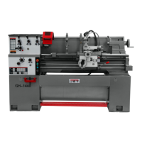
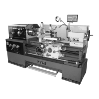
4.4 Machine description
Fig 1
A….Lathe bed
B….Carriage
C….Top slide
D….Cross slide
E….Four-way tool post
F….Headstock
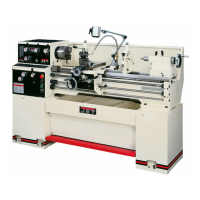
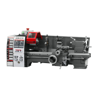
Fig 2
A….Apron
B….Tailstock
C….Lead screw
D….Feed rod
E….Gear box
F….Steady rest
G….Follow rest
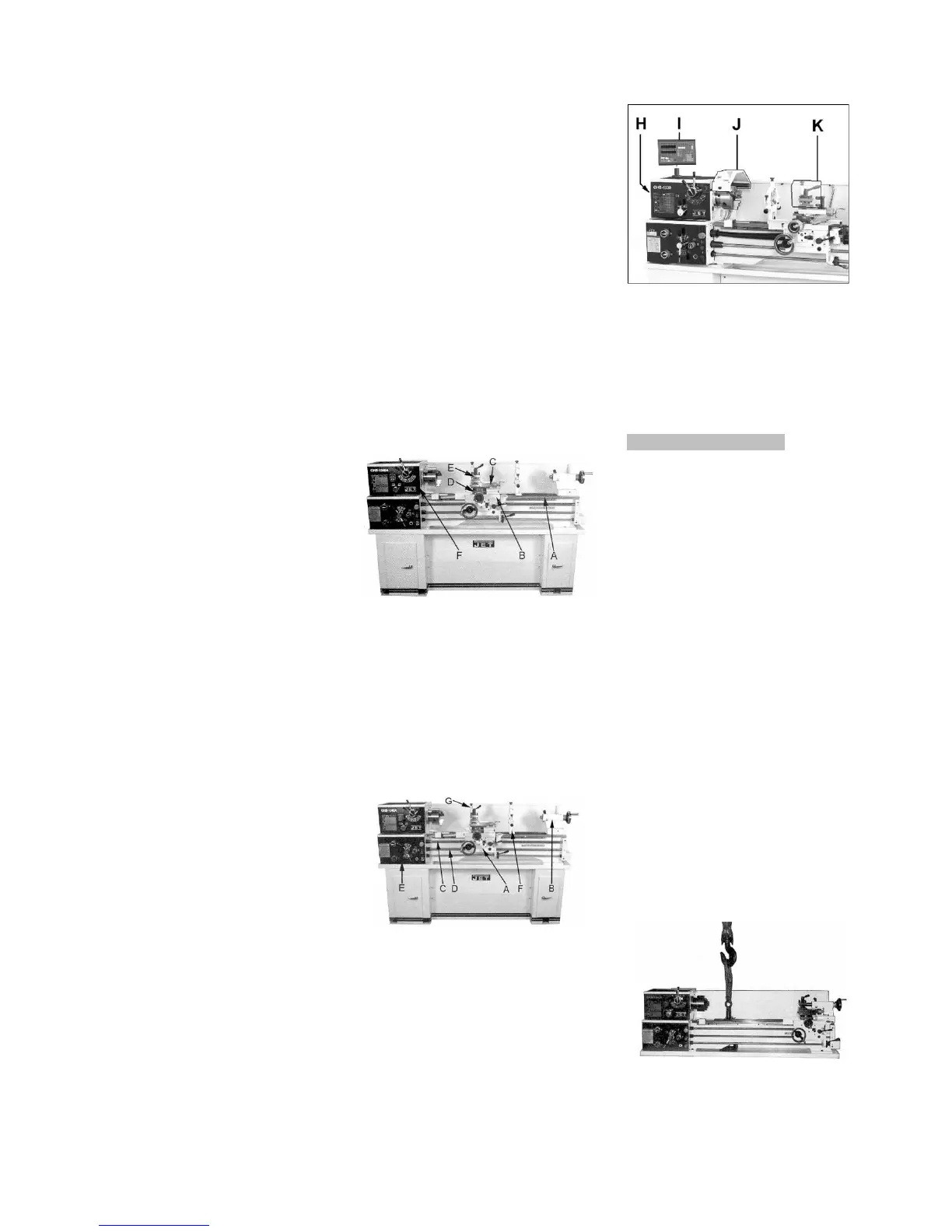
Fig 3
H….Pulley cover
I…...3-axis digital readout (option)
J.….Chuck guard
K….Tool post guard
5. Transport and start up
5.1 Transport and installation
The machine will be delivered in a
closed crate.
For transport use a forklift or hand
trolley. Make sure the machine does
not tip or fall off during transport.
The machine is designed to operate in
closed rooms and can be bolted to the
floor.
5.2 Assembly
If you notice transport damage while
unpacking, notify your supplier
immediately. Do not operate the
machine!
Dispose of the packing in an
environmentally friendly manner.
Clean all rust protected surfaces with
petroleum, diesel oil or a mild solvent.
Unbolt the lathe from the shipping
crate bottom.
Move the carriage and tailstock to the
tailstock end of the bed.
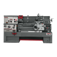
Assemble lifting hook (parts fastened
to the crate bottom) to lift the lathe
(see Fig 4)
Fig 4