Do you have a question about the Jet BDB-919 and is the answer not in the manual?
Details on grounding tools for electrical safety and risk reduction, emphasizing proper plug and outlet use.
General safety precautions applicable to all tools, emphasizing reading manuals and maintaining safe work areas.
Lists all parts included in the lathe's shipping container with reference to figure numbers.
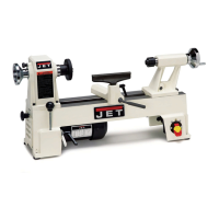
Details the material and construction of the lathe bed for rigidity and low vibration.
Explains the headstock construction, spindle mounting, and belt change mechanism.
Describes the carriage, cross slide, and top slide, including adjustments and tool post mounting.
Details the apron's mounting, half nut engagement, and how it facilitates quick apron travel.
Explains the tailstock's movement, clamping, spindle, and taper socket.
Describes the mounting and function of the lead screw for automatic feed, including play adjustment.
Guides on correctly setting tool height and minimizing tool overhang for optimal cutting.
Explains how to use handwheels for longitudinal and cross feeding during manual turning operations.
Details the procedure for engaging the automatic feed for longitudinal turning operations.
Describes how to create tapers by offsetting the tailstock and securing the workpiece.
Explains the method for turning tapers by angling the top slide, suitable for short tapers.
Covers cutting standard inch threads using the half nut and threading dial, referencing charts.
Details the procedure for cutting metric threads, emphasizing continuous half nut engagement.
Describes the function and clamping capabilities of the three-jaw universal chuck.
Outlines the process for adjusting main spindle bearings if end play becomes evident.
Explains how to adjust the cross and top slide gibs for proper fit and reduced play.
Details the procedure for adjusting the compound feed screw and its nut to eliminate play.
Describes how to adjust the cross slide screw to eliminate backlash between the spindle and nut.
Explains how to adjust the half-nut guides for free movement without play.
Provides step-by-step instructions for safely removing and replacing the V-belt on the lathe.
Visual diagram showing all components of the headstock assembly with index numbers.
List of parts for the headstock assembly, including part numbers, descriptions, sizes, and quantities.
Exploded view of the drive belt assembly, illustrating all constituent parts.
Detailed list of parts for the drive belt assembly, with part numbers and specifications.
Diagram showing the exploded view of the belt tension lever mechanism.
Exploded view illustrating the various change gears and their mounting hardware.
Exploded diagram of the lathe's electrical components and their arrangement.
List of electrical parts, including part numbers, descriptions, and quantities.
Exploded view of the chuck guard assembly, showing its components.
Exploded view of the gear box assembly, illustrating its internal gears and parts.
List of parts for the gear box, including part numbers and specifications.
Exploded view of the apron assembly (Version I), showing all parts.
Parts list for Apron I, detailing components, part numbers, and quantities.
Exploded view of the apron assembly (Version II), showing its components.
Exploded view of the saddle and cross slide assembly, illustrating its parts.
Parts list for the saddle and cross slide, with part numbers and quantities.
Exploded view of the compound slide assembly, showing its components.
Parts list for the compound slide, detailing components, part numbers, and quantities.
Exploded view of the tailstock assembly, illustrating its parts.
Parts list for the tailstock, with part numbers and quantities.
Exploded view of the steady rest assembly, showing its components.
Exploded view of the follow rest assembly, illustrating its parts.
Exploded view of the BD-919 bed assembly, showing its components.
Parts list for the BDB-919 bed assembly, detailing components, part numbers, and quantities.
Exploded view of the BDB-929 bed assembly, illustrating its parts.
Parts list for the BDB-929 bed assembly, with part numbers and quantities.
Exploded view of various lathe accessories, showing their components.
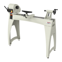
Exploded view of the optional stand for BDB-919, showing its parts.
Exploded view of the optional stand for BDB-929, illustrating its parts.