9
Assembly
Tools required for assembly:
Wrenches, 10, 13 and 14mm
NOTE: A ratchet wrench with sockets may
speed assembly time
Set of hex (Allen) wrenches
Cross-point (Phillips) screwdriver
Exposed metal surfaces on the mortiser have
been factory-coated with a protectant. This
should be removed with a soft rag moistened
with kerosene or a light solvent. Do not use an
abrasive pad and do not use gasoline, paint
thinner or acetone, as these will damage plastic
components and painted surfaces.
The mortiser should be placed in a dry area with
a level floor and good lighting. Provide enough
space around the mortiser to allow for
operations and any adjustments or servicing.
Mounting to Stand
The mortiser is heavy!
Assembly to the stand requires an assistant
or a hoist.
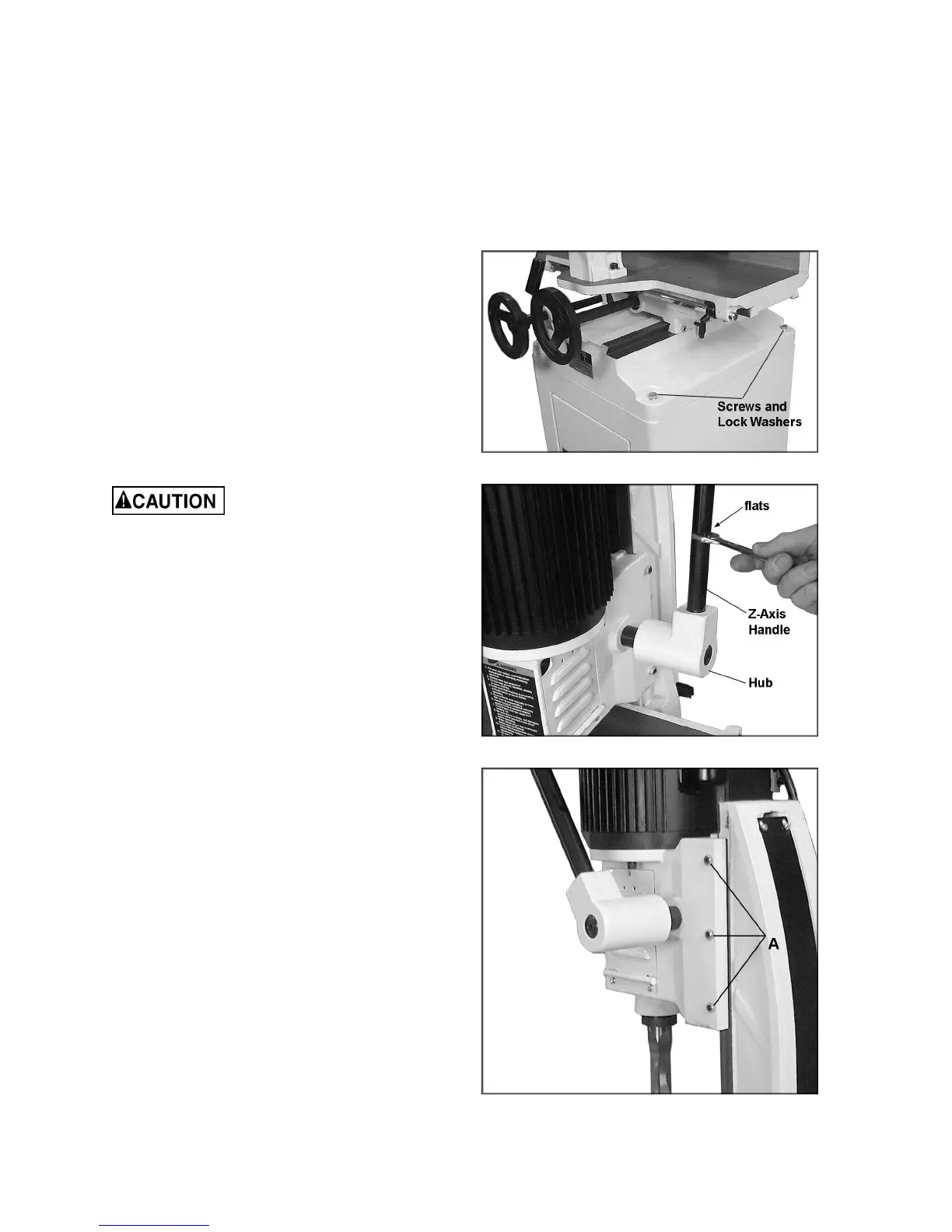
Place the mortiser upon the stand, making sure
the front of the mortiser faces the same direction
as the door in the stand. Line up the four holes
in mortiser base and stand, and insert four M8 x
45 hex cap screws with four M8 lock washers
(see Figure 3). Tighten securely with a 13mm
wrench.
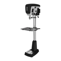
Z-Axis Handle
Screw the handle into the hole on the hub
(Figure 4). Tighten by turning a 14mm wrench
on the flats of the handle, as shown.
The hub is spring loaded and can adjust the
handle to different positions for the operator’s
convenience. Pull outward on the handle close
to the hub and rotate it into position, then
release, allowing it to drop back onto the pin.
Make sure the hub re-seats itself on the pin.
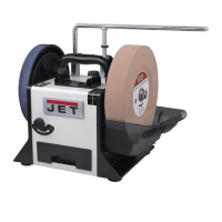
IMPORTANT: If the head will not move when
the handle is operated, the head may have been
tightened for shipping purposes. To free the
head, loosen the three hex nuts (A, Figure
)
with a 10mm wrench (do not remove), and then
slightly loosen the set screws within them using
a hex wrench. Caution: The head may rise
when the set screws are loosened.
Re-tighten the hex nuts (A, Figure 5) while
continuing to hold the set screws to prevent
them from turning during the tightening process.
Figure 3
Figure 4
Figure 5