7
Figure 4
7.0 Assembly
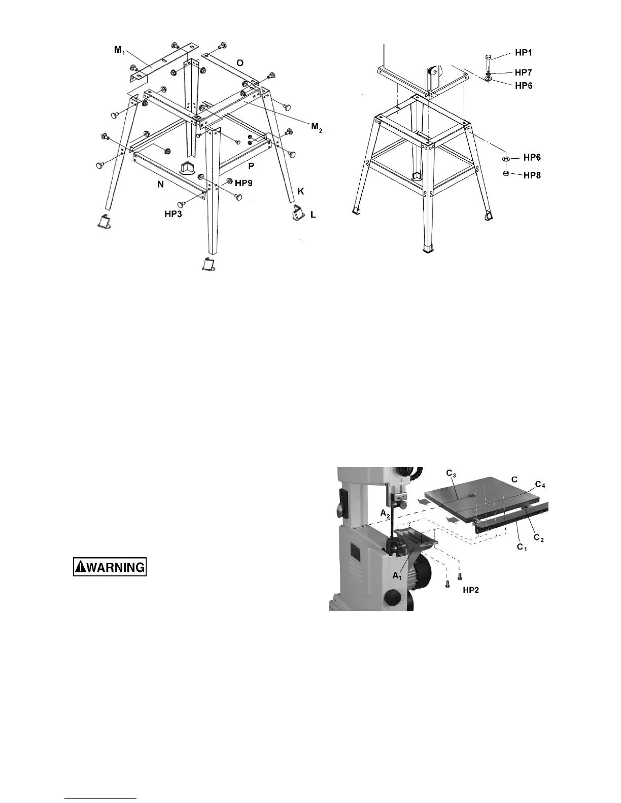
7.1 Stand assembly
1. Refer to Figure 4 to assemble stand. Use
carriage bolts (HP3) and flange nuts (HP9)
throughout. Only hand-tighten all fasteners at
this time.
2. Make sure the two short support plates with
extra holes (M) are opposite one another as
shown.
3. Slip rubber feet (L) onto ends of stand legs.
4. Place stand upright on level floor, and push
down until it sits evenly.
5. Tighten all nuts on stand assembly.
7.2 Mounting saw to stand
Use an assistant to help lift
band saw onto stand.
Align holes on saw base with holes in stand. Mount
saw to stand using three hex cap screws, with
washers and nuts, as shown in Figure 300. Tighten
nuts.
7.3 Table installation
Refer to Figure 5.
1. Loosen lock handle (shown in Figure 9) and
pivot trunnion (A
1
) to horizontal position.
2. Loosen lock knob (C
2
) and pull extension (C
1
)
out from the table (C).
3. Orient table as shown, then maneuver to allow
saw blade (A
2
) to pass through slot (C
3
) to the
center.
4. Line up four threaded mounting holes
underneath table with the four mounting
through-holes on trunnion.
Important: Adjust table so miter slot (C
4
) is parallel
with saw blade (A
2
).
5. Secure with four M6x12 hex washer head
screws (HP2). Tighten with 13mm wrench.
Figure 5
 Loading...