9
Table Assembly
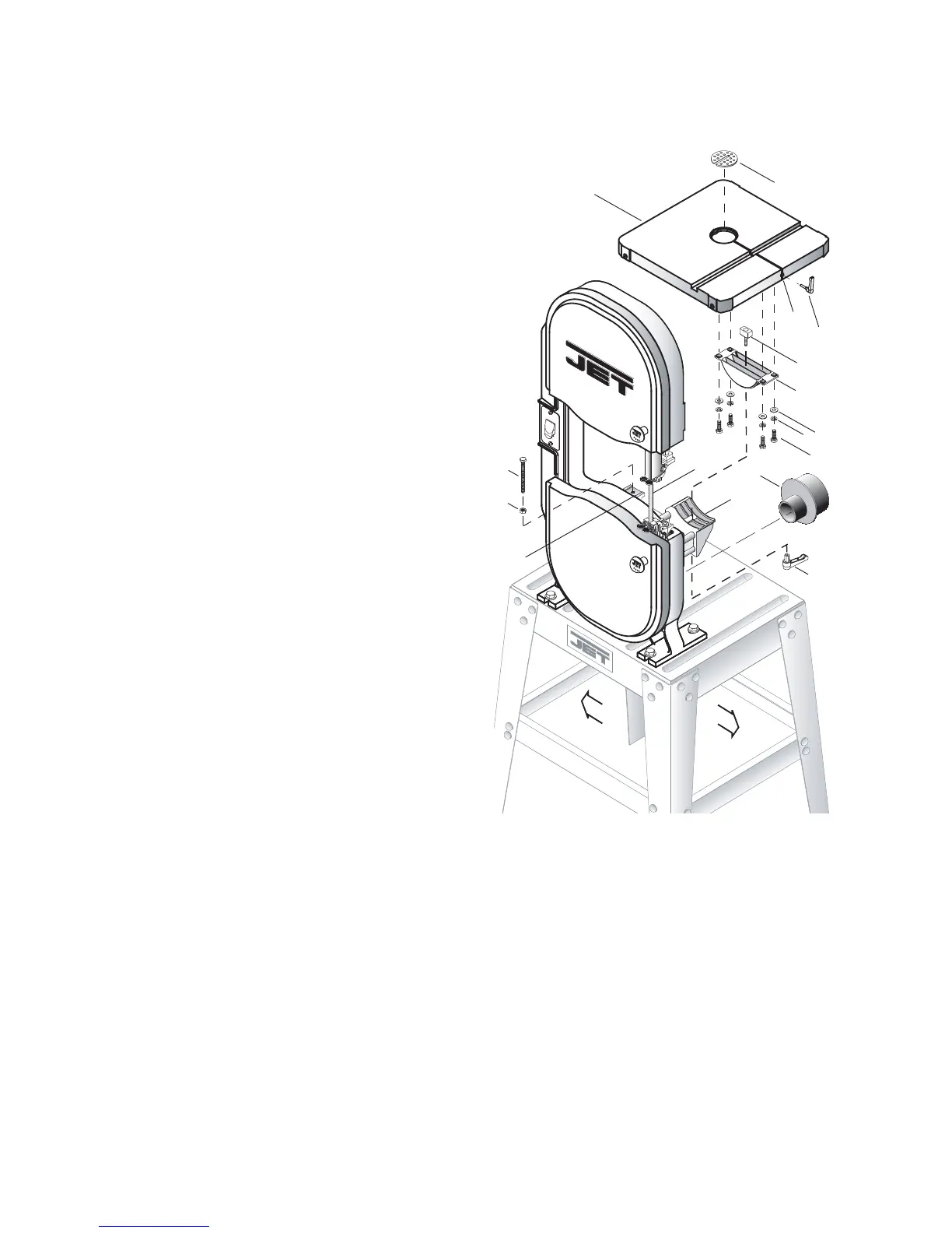
For this section, refer to Figure 3.
90º Table Stop
1. Thread the M6 hex nut (R) approximately half
way onto the M6x70 hex cap screw (M). Then
thread the screw half way into the bracket (A
B
).
Adjustment will be made later.
Trunnion Installation
2. Position the trunnion (C) on top of the trunnion
support bracket (C
C
). The scale on the trun-
nion must be on the same side as the indicator
arrow on the bracket.
3. Place the clamp shoe (C
A
) through the middle
slot at the top of the trunnion (C), inserting the
screw through the slotted opening at the
bottom of the trunnion and through the support
bracket (C
C
).
4. Thread the lock handle (C
B
) onto the screw
protruding through the bottom of the support
bracket (C
C
). Adjust the trunnion (C) to 0º, then
secure by tightening the lock handle (C
B
).
Table Installation
5. Remove the insert (B
A
) and pin (B
B
) from the
table (B).
6. Maneuver the table (B) to allow the saw
blade (A
A
) to pass through the slot (B
C
) to the
round opening in the center.
7. Orient the table (B) as shown.
8. Line up four threaded mounting holes
underneath the table (B) with the four mount-
ing through-holes on the trunnion (C).
9. Secure with four each M8x20 hex cap
screws (O), M8 lock washers (S) and M8xØ18
flat washers (T).
10. Tighten the screws (O) with a 13mm wrench.
Right
T
C
C
A
C
B
S
O
B
A
B
B
B
D
C
C
B
C
Left
A
A
M
R
A
B
Figure 3
 Loading...