18
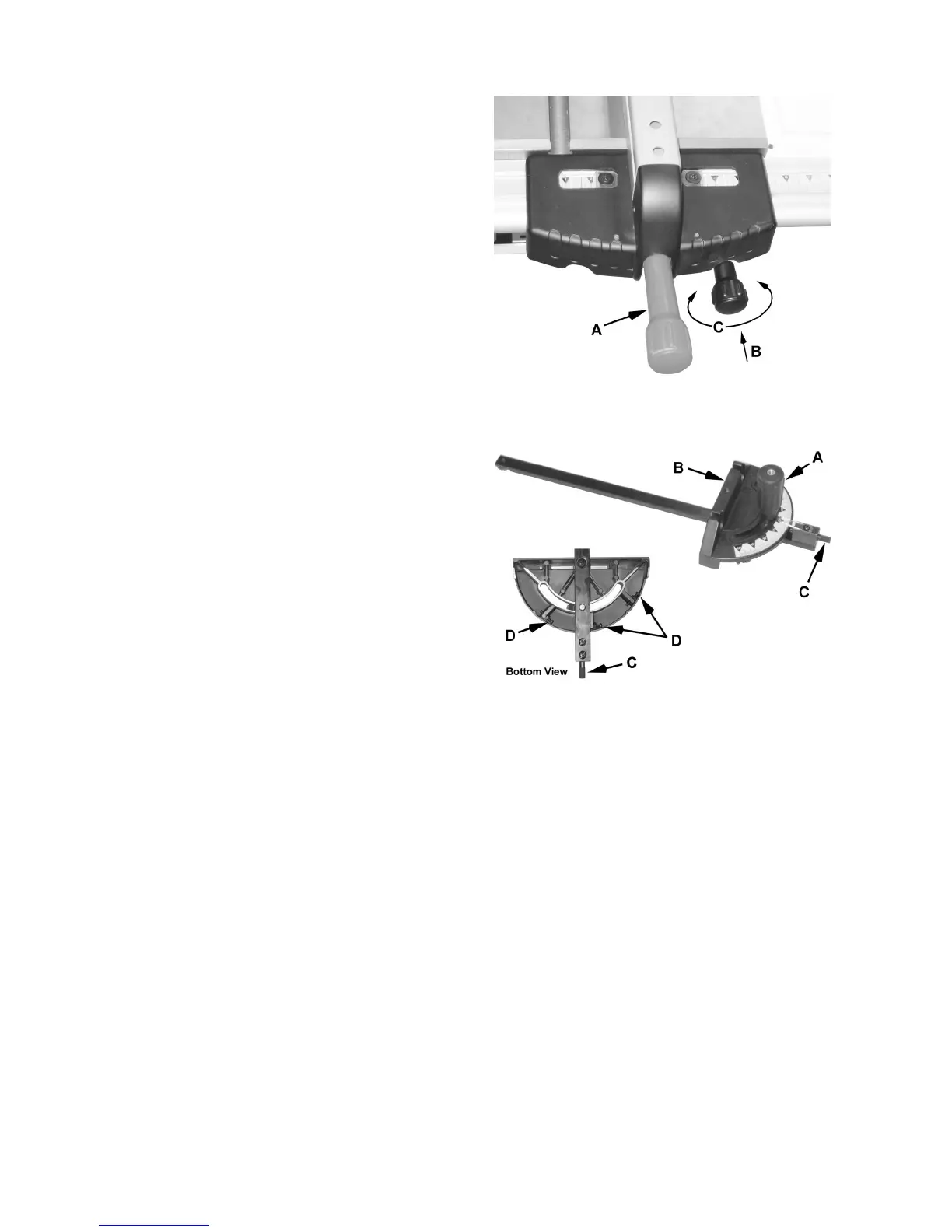
This fence is positioned by lifting up the lock handle
(A, Fig. 19) and sliding to the desired location.
"Fine-tuning" is accomplished by pushing the
micro-adjust knob in (B, Fig. 19) and at the same
time turning it (C, Fig. 19) until the exact position is
read on the scale.
Miter Gauge
Operation
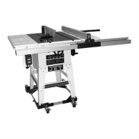
Referring to Figure 20:
Operate the miter gauge by loosening the lock
knob (A) and turning the miter body (B) to the
desired angle.
The pin (C) functions as an index stop. When
pushed in, the body will stop at -45º, 90º or +45º
when turned as one of three screws (D) located
underneath the miter hits the pin.
Calibration
If a miter angle at the -45º, 90º or +45º is not
correct, the index stops can be adjusted by turning
one of three adjustment screws (D), then locking
the hex nut.
Note: Always make test cuts. Do not rely solely on
miter gauge indicator marks.
Figure 19
Figure 20