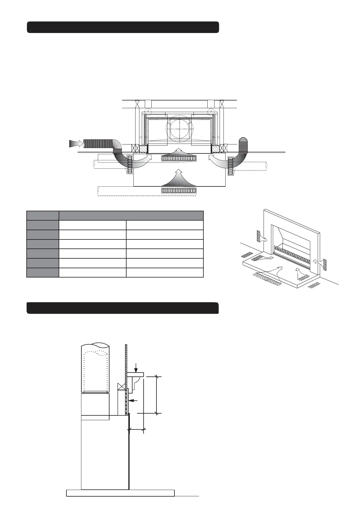
MODEL MINIMUM VENT SIZE (x2)
Square Design (L x H) Rectangle Design (L x H)
700 100 x 100 200 x 50
850 125 x 125 250 x 50
1050 150 x 150 250 x 100
1200 175 x 175 350 x 100
1500 200 x 200 400 x 100
A
B
D
C
C
B
A
Dimensions in mm
Table 5
Note: Table 5 dimensions are internal dimensions only, does not include vent flange
AIR REPLACEMENT PREPARATION
The Fireplace Ltd specifies that allowances must be made for air replacement vents to be located near the fireplace,
to aid combustion and reduce the incidence of back venting. Refer below for air vent sizing and suggested location.
Fig. 26 - Location points A,B,C,D are suggested combinations. A minimum of one pair of air vents is
recommended or one large vent, as per location point D. Allowance to be made for minimum 2 inlet ducts from outside
to internal vent location.
Note: DO NOT USE FIREPLACE CAVITY VENTILATION AS A METHOD OF AIR REPLACEMENT.
Fig. 25
6.TMWG.16
(from the outside through the side wall)
(from the outside through the floor)
Floor Protector
Air Replacement Ducts
Fig. 26
X
Y
1
23
4
5
6
Notes:
1. Mantel / Surround
2. Tile or margin facing (non combustible material)
3. Hebel Block
4. Firebox
5. Gather
6. Flue
X See Fig. 28
Y See Fig. 28
Fig. 27
Drawing Not To Scale
CLEARANCE TO COMBUSTIBLE MANTELS