X
Y
X
Y
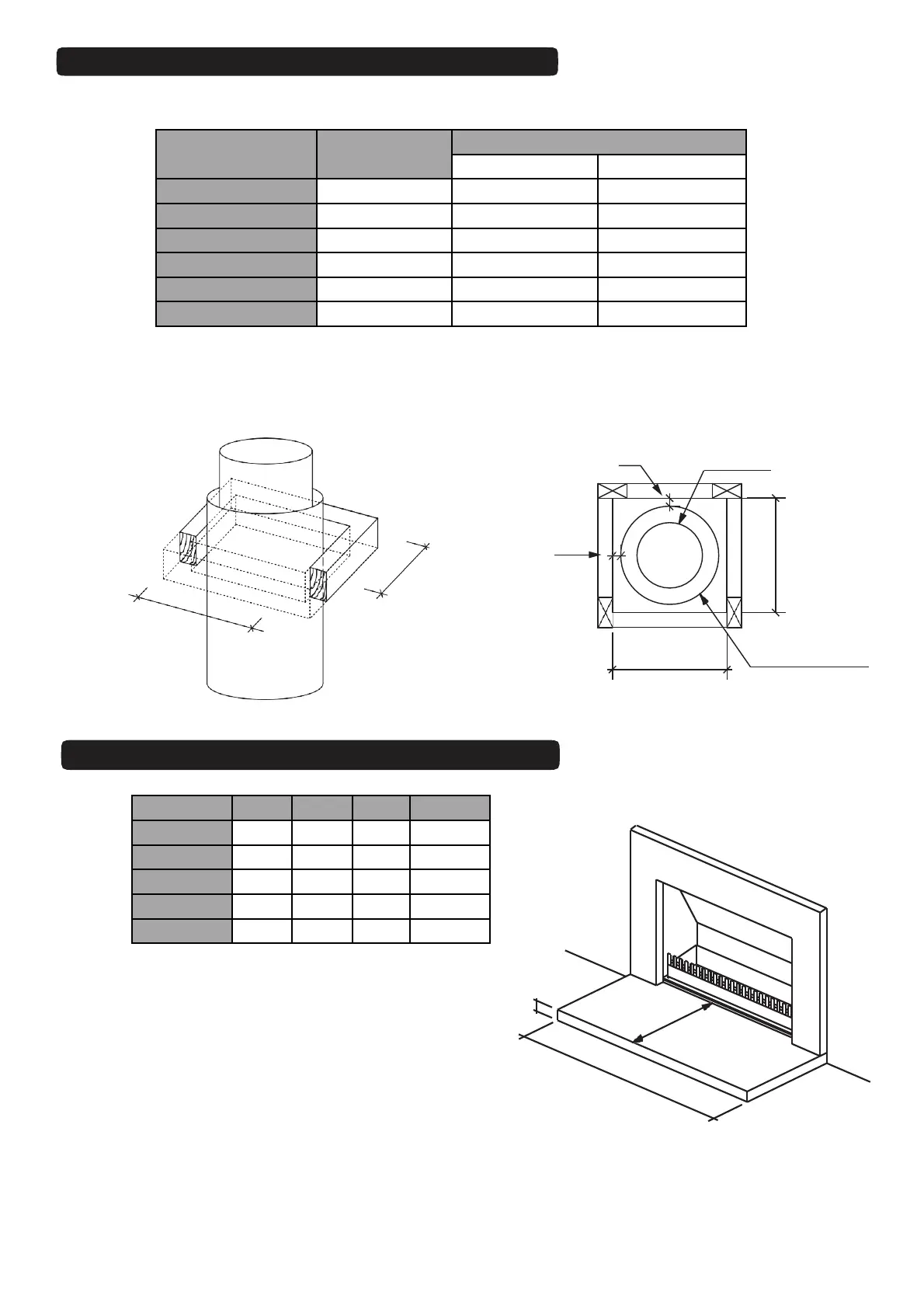
Flue Pipe
Min. 25mm Clearance
Min. 25mm Clearance
Flue Pipe Casing
Dimensions in mm
Note: A minimum 25mm clearance from flue pipe casing to combustible material must be maintained.
A Minimum clearance of 200mm above Heat Shield must be maintained.
Fig. 23
MODEL FLUE SYSTEM MINIMUM TRIM OUT DIMENSION
X (min) Y (min)
700 225/325 375 375
850 250/350 400 400
1050 IGC 250/300 350 350
1050 300/400 450 450
1200 400/500 550 550
1500 450/550 600 600
Table 4
CHIMNEY CHASE MINIMUM TRIM OUT
6.TMWG.15
MODEL A B C * GAS - B
700 1100 400 75/8 300
850 1250 450 75/8 300
1050 1450 600 75/8 300
1200 1600 750 75/8 -
1500 1900 850 75/8 -
B
C
A
* A minimum 75mm thickness refers only to Hebel Block – for solid fuel installations. Minimum 100mm thickness
required if poured concrete
* Minimum of 8mm thickness refers only to Gas burners installations.
.
Table 5
Fig.24
MINIMUM FLOOR PROTECTOR SIZE