Table 3
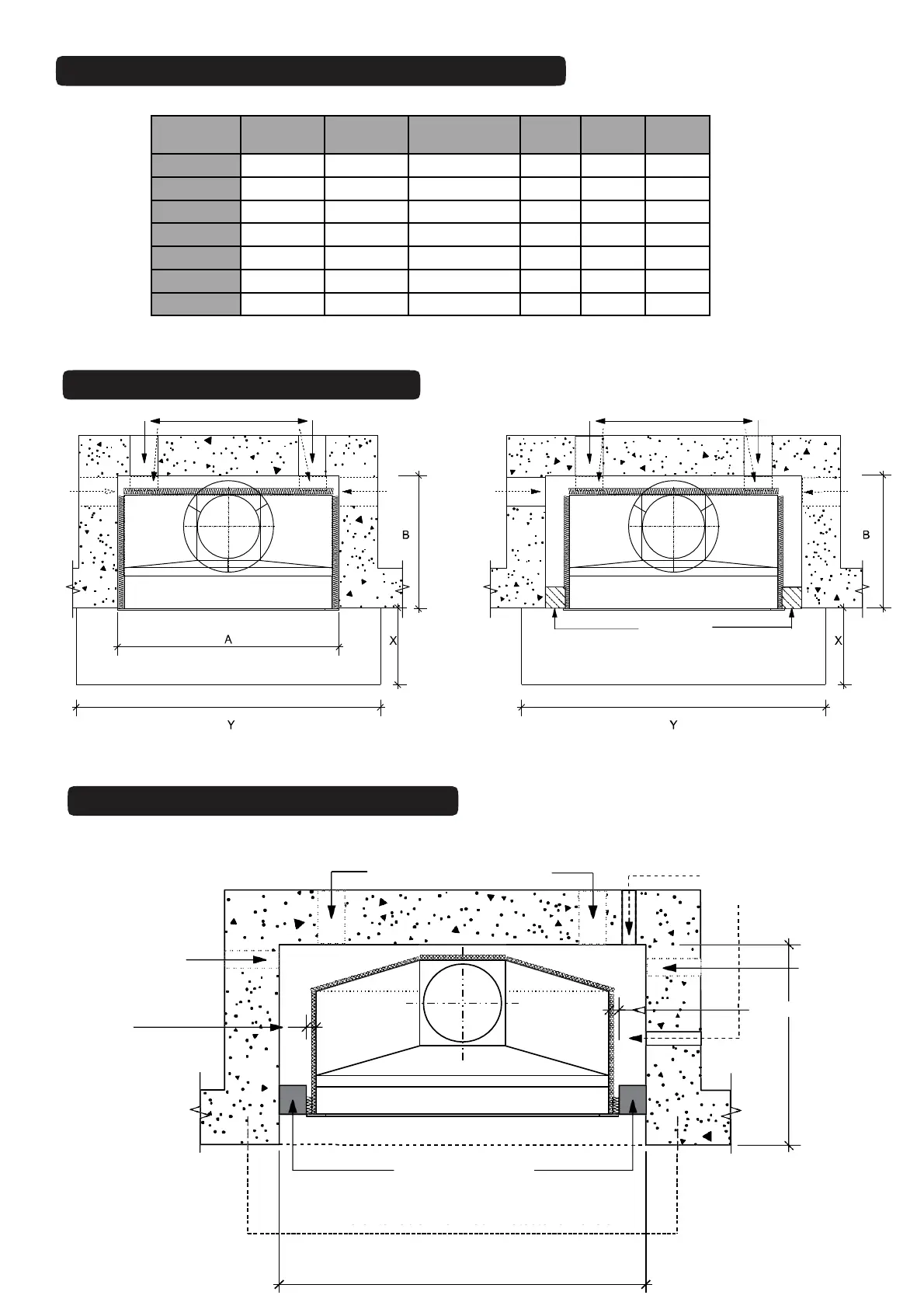
MASONRY MINIMUM CAVITY SIZE
6.TMWG.9
PLAN VIEW
Drawings Not To Scale
min 2 x 100 x 50mm or 80mm diam wall
or floor mounted air vents
concrete block
or hebel block
air vents
air vents
air vents
air vents
Fig. 12
Y
Fig. 13
Y
Fig. 11
PLAN - RECESS DETAIL
Fig. 14
min. 25mm clearance
25
25
min. 25mm clearance
B + recessed
Masonry or Hebel block
minimum ‘A’
‘X’ - Refer toTable 2 for Floor Protector dimension
RECESS REQUIRED (40mm Min. 100mm Max)
Allow gas line into
firebox
(if applicable)
Air Vent
‘
Y’ - Refer toTable 2 for
Floor Protector dimension
Air Vent
min. 2 x 100 x 50mm or 80mm diam
wall of floor mounted air vents
Drawings Not To Scale
MODEL A B
Temporary
Lintel
X min* Y min* Z min*
700 800 470 1200 400 1100 75
850 950 530 1200 450 1250 75
1050IGC ** 1150 450 1200 300 1450 8
1050LL 1150 565 1200 600 1450 75
1050U 1150 565 1200 600 1450 75
1200 1300 785 1500 750 1600 75
1500 1600 800 1500 850 1900 75
**1050IGC box is ONLY available for a GAS installation