Please note that these dimensions (based on Hebel Block margins) are the absolute minimum sizes - widths (A & C)
maybe increased if desired.
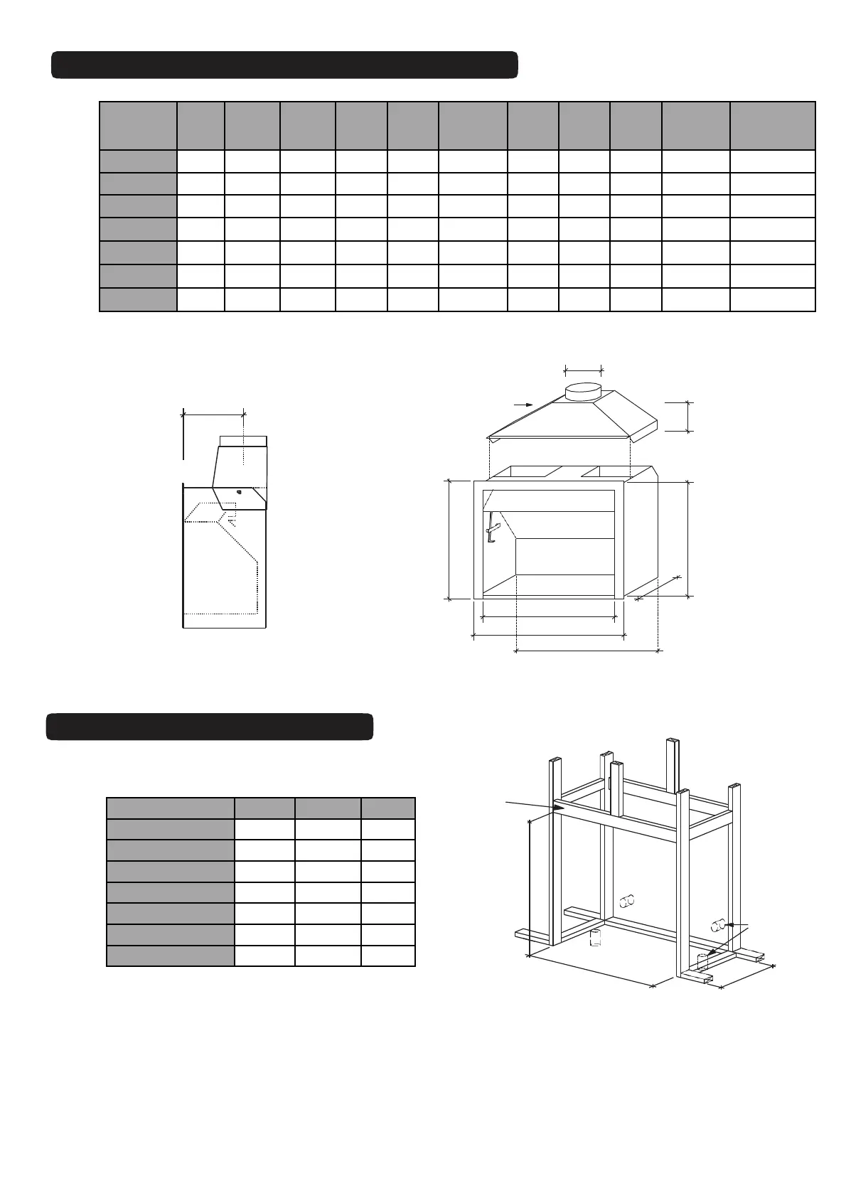
It is important to ensure the Jetmaster firebox is seated on top of the finished floor protector level.
Gather
D
E
C
A
A1
B
F
A2
Fig. 2
Y
Front
Back
Gather
B
A
C
Table 1
Table 2
Fig. 3
Air
Vents
Fig. 4
All front
nogs
to be
installed
on edge
TIMBER FRAME DIMENSIONS
JETMASTER FIREBOX DIMENSIONS
6.TMWG.4
* Twin flue gather available **1050IGC Box is ONLY for gas installations
MODEL A A1 A2 B C D E F Y
Off-set
Gather
Indoor
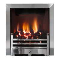
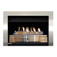
Gas
Burner
700 700 800 750 400 700 225/325 200 680 295 395 Yes
850 850 950 900 450 700 250/350 220 680 322 422 Yes
1050IGC ** 1050 1150 1100 335 650 250/300 240 630 250 445 Yes
1050LL 1050 1150 1100 500 700 300/400 240 680 345 445 Yes
1050U 1050 1150 1100 500 800 300/400 240 780 345 445 -
1200 * 1200 1300 1250 600 1020 400/500 400 1000 435 - -
1500 * 1500 1600 1550 600 1020 450/550 410 1000 435 - -
MODEL A B C
700 960 1200 525
850 1110 1200 560
1050 IGC 1310 1200 450
1050 LL 1310 1350 610
1050 U 1310 1450 785
1200 1500 1620 785
1500 1800 1620 810