www.JFY-tech.com
9
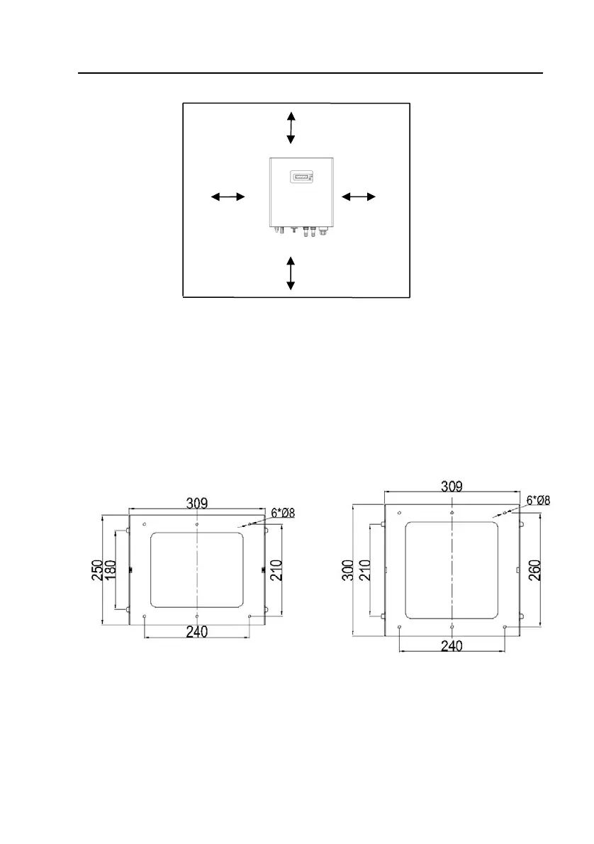
200mm (8”)
200mm (8”)
200mm (8”) 200mm (8”)
Fig.2 Installing minimum clearances around inverter
2.3 Fixed on the wall
Step1: Drill 6 or 9 holes as illustrated in the Fig.3
Step2: Fix the mounting frame as illustrated in the Fig.4 by the screws, then, hang
the inverter on the mounting frame.
Step3: Fix safety-lock screws at left side and right side as illustrated in Fig.5
with the attached socket head wrench.
Step4: Check the installation conditions.
For JSI-1500TL/-S For JSI-2000TL/-S, JSI-2500TL/-S,
JSI-3000TL/-S and JSI-3600TL/-S