11
QUATTRO MANUAL
The final step in your flight pack installation will be
to determine the amount each control surface will
move on your model at full transmitter stick
deflection. Please refer to your aircraft’s instruction
manual for suggested travel limits.
It is possible to increase/decrease the amount that
your control surface moves at full stick deflection
by mechanical adjustments.
It is imperative that the servo does not attempt to
push/pull the control surface past its mechanical
limits. This condition is called “binding.” When a
servo moves a control surface into a “binding”
position, the servo itself then becomes “stalled,”
unable to reach its full deflection. This condition is
both harmful to your control linkage and to your
servo. This “stalled” condition will also force the
servo to drain power more quickly from your flight
pack battery, thereby reducing your usable flying
time. Fortunately, servo “stalling” is usually easy to
detect by either a “buzzing” or “humming” sound
which comes from the stalled servo.
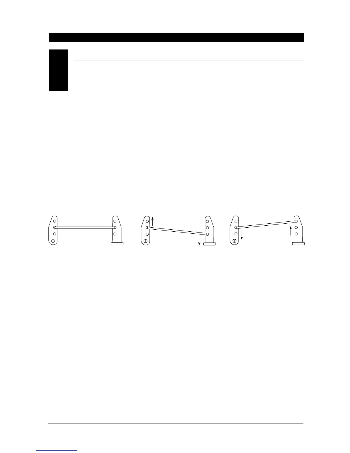
The following diagram is designed to help clarify
how to increase or decrease control surface travel
mechanically to eliminate control surface “binding”
and servo “stalling.”
To increase control surface travel, select a linkage
attachment point further outward on the servo arm
or further inward on the control horn closer to the
control surface (Figure 2).
To reduce control surface travel, select the linkage
attachment point close to the center of the servo
area or further out on the control horn on the
control surface (Figure 3).
Quite simply, by moving the control rod in on the
servo arm/wheel, control surface travel will be
reduced, and by moving the control rod out on the
servo arm, the control surface travel will be
increased. The opposite holds true for the control
surface arm (horn) as well. You may also use any
combination of these positions to achieve proper
control surface/servo travel.
NOTE: Once the appropriate servo arm/wheel and
control rod location has been established, secure
the servo arm to the servo output shaft using the
original servo horn screw.
Control Rod
Figure 1 Normal (Linear)
Linkage Set Up
Figure 2 Increased Control
Surface Movement
Figure 3 Reduced Control
Surface Movement
Servo Arm
Control Surface
Arm (Horn)
Control Surface
Arm (Horn)
Control Surface
Arm (Horn)
Servo Arm
Servo Arm
Control Rod
Control Rod
ADJUSTING CONTROL SURFACE TRAVEL
10.4
 Loading...