33
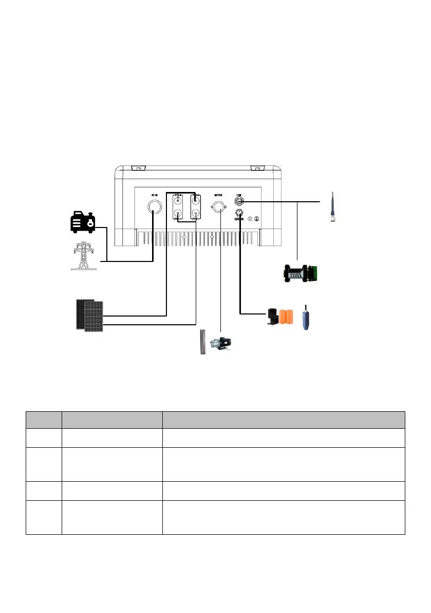
6.2 Schematic Diagram of Electrical Connection
Figure 6-2 is the schematic diagram of electrical connection among PV arrays,
Solar Pump Inverter and three phase AC pump. Water level sensor and
communication interface shall be connected if needed.
A. PV array
F. GPRS
module
E. Water level
sensor
C. Water pump
D. RS485 module
Solar pumping inverter
B. Power grid or
generator
+
-
Figure6-2 Electrical connection diagram of Solar Pump Inverter
Table6-2 Equipment list of Solar pump system
The max. Voc of each string is 880V.
Power grid, diesel generator or other AC input
sources.
Three-phase alternating current pump
Optional, can be purchased from Supplier
 Loading...