41
connector" in the machine packing box, using the way of wiring.
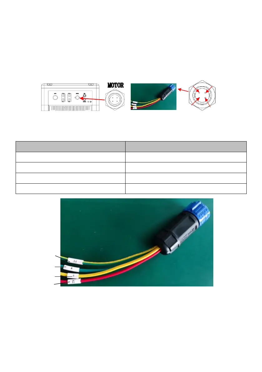
Step 2: insert inverter output connector into the inverter "MOTOR" port, and
tighten. As shown in the figure below:
Figure 6-7 Motor connector terminal schematic
Table 6-4 Description of connecting pins for water level sensors
Port (Sensor) connector pin
Figure 6-8 Motor connector line sequence nameplate schematic


 To Next Page