48
Table 6-5 COM terminal pin definition on machine panel
RS485 communication port A
RS485 communication port B
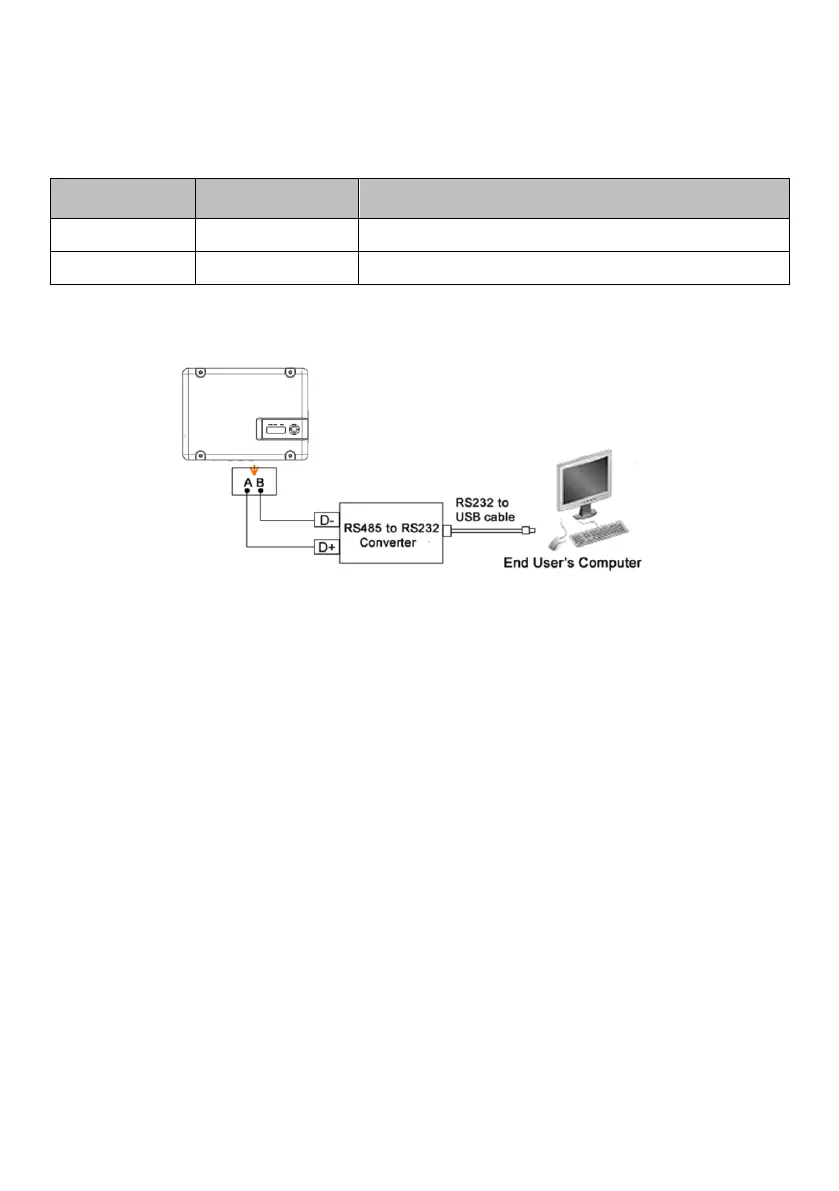
The following diagram guide you to connect a single inverter to monitoring equipment.
Figure6-16 Diagram of single communication wiring
The wiring diagram is schematic diagram, just take HEXIN converting module
as an example. If the user choose other converter, need according to the
converter‘s instructions, wiring the inverter’s A, B wires to the converter’s
correct terminal.
Please refer to “Inverter Management System User Manual” for the
corresponding monitoring software settings, after completing the wire
connection.


 To Next Page