18
2.0-1
D.
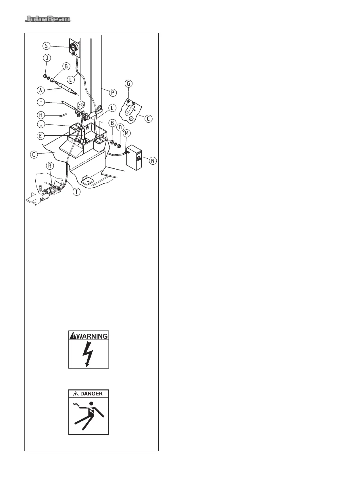
Tilt the column backwards. Pull the rod “E” of the tilting
cylinder and connect it to the column with the pin “F”.
Apply N°243 Loctite to the grub screw “H” and tighten
with a tightening torque of 11 Nm.
E.
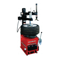
Fix the manometer ‘S’ with the available screws, as
shown in Fig. 2.0-1.
F.
Connect the air hose ‘L’ (Fig. 2.0-1) coming from the
tool box ‘S’ (Fig. 2.0-1) to the ! tting ‘M’ of the device
‘N’ (Fig. 2.0-1).
G.
Mount the carter ‘U’ (Fig. 2.0-1), by tightening the
screws ‘Z’.
Mount the lube pail with the available screw.
H.
Secure the tire changer to the " oor as described in
chapter 2.2.
2.1 ELECTRICAL INSTALLATION
WARNING!
THE ELECTRICAL INSTALLATION MUST BE MADE
BY A LICENSED ELECTRICIAN.
Check that the electrical speci! cations of the power
source are the same of the machine. The machine
uses 115 V AC 60 Hz, single phase 20 amp source.
Electric speci! cations are clearly marked on a label at
the end of the electric cord.
If the plug is provided disregard this paragraph.
Connect the electric cord of the machine with an
approved plug. The ground cable (green and yellow)
must be properly connected.
DANGER
FAILURE TO PROVIDE PROPER ELECTRICAL
SUPPLY AND GROUNDING WILL CREATE A
SHOCK HAZARD TO THE OPERATOR.