40
5.2-1
5.1-1
5.1-2
5.1-3
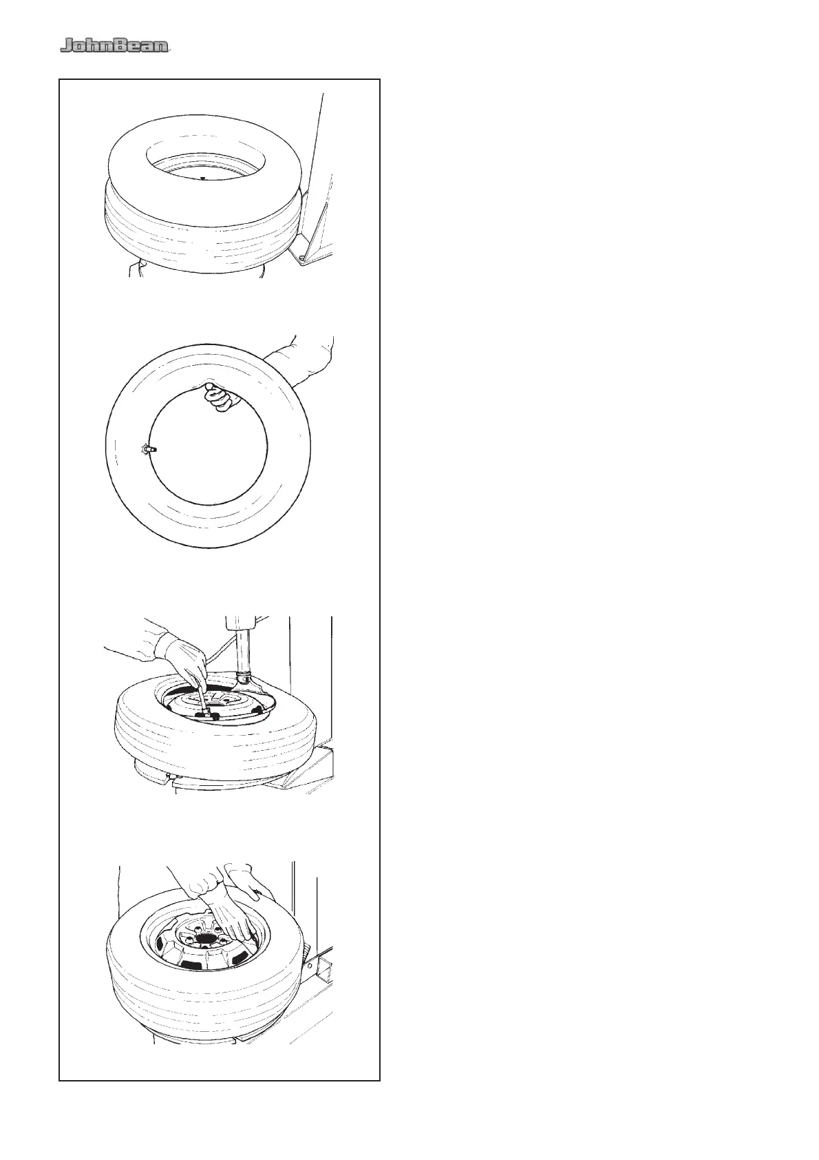
5.1 Mounting tube-type tires
A. Proceed as described in section 4.2.A.
Do NOT lubricate the tube. Talc can be used to assist
with the tube positioning.
B. Mount the valve core and place the tube onto the tire
to con! rm that the tube is of the correct size (Fig. 5.1-1).
C. In" ate the tube slightly: if held with the index ! nger
it should bend a little (Fig. 5.1-2).
D. Mount the ! rst bead as described in section 4.2.B.
Put the tube inside the tire and secure the valve with
the chuck of the in" ating hose (Fig. 5.1-3).
Mount the top bead following the directions above.
5.2 In! ating tube-type tires
To in" ate the tires unlock the rim and start in" ating
while pressing the valve towards the inside. This is
necessary to avoid air pockets forming between tube
and tire (Fig. 5.2-1).
Ensure that the tire is correctly centered on the rim and
complete in" ation as described in section 4.3.
5.0 Demounting tube-type tires
A. For breaking the bead operate as described for the
tubeless tires in § 4.1.A to 4.1.F.
In this case, the valve is part of the tube
WARNING: BE CAREFUL NOT TO DAMAGE
THE TUBE DURING THE BEAD-BREAKING
OPERATION. THE VALVE SHOULD BE OPPOSITE
TO THE BLADE OF THE BEAD BREAKER.
NOTE: In order to avoid damage to their surface
! nish, alloy rims should be clamped from
the outside only.
Special plastic caps are available as optional extras
for the clamping jaws so that alloy rims
can be clamped carefully.
B. To demount the ! rst bead, place the valve at 3
o’clock position.
WARNING
DO NOT CATCH THE TUBE WITH THE BEAD
LIFTING TOOL, WHEN LIFTING THE BEAD ON
THE MOUNTING FINGER
After demounting the ! rst bead remove the tube before
demounting the second bead, as described in section 4.1.