A19A
Issue 03/03/2003
© 2003 Johnson Controls Inc.
Catalogue Section 1
Order No. PD-A19A-E
3
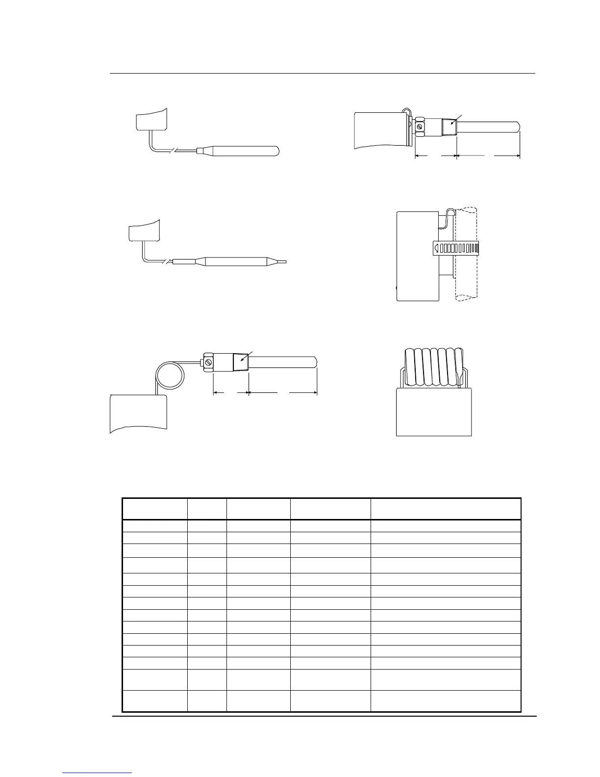
S
ensor styles
Fig. 4
Style 1a (drawn bulb)
Fig.5
Style 1b swaged bulb, can be used with
closed-tank connector FTG13A-600
½" x 14 NPT
33.3 60
Fig. 6
Style 4h
½" x 1 4 NP T
58.3
60
Fig. 7
Style 2
Fig. 8
Style 20
Fig. 9
Style 3 (coil)
B
ulb size and finish, bulb wells
Range (°C) Style Bulb size
(mm)
Finish Bulb well (optional)
-35 to +10 1b 9.5 x 110 Tin-plated WEL14A602R
-35 to +10 3 - Stainless Steel -
-5 to +28 1b 9.5 x 135 Tin-plated WEL14A603R
-5 to +28 3 - Stainless Steel -
-35 to +40 1b 9.5 x 110 Tin-plated WEL14A602R
-35 to +40 3 - Stainless Steel -
0 to 13 1a 9.3 x 80 - WEL16A601R
0 to 43 3 - Stainless Steel -
1 to 60 1b 9.5 x 115 - WEL14A602R
5 to 32 1b 9.5 x 155 Tin-plated No bulb well available
10 to 95 1a 7.4 x 75 - WEL11A601R
40 to 120 1b 9.5 x 100 - WEL14A602R
35 to 150 1a 5 x 265 - No bulb well or closed tank
connector possible
90 to 290 1a 5 x 155 - No bulb well or closed tank
connector possible