22 Addressable Intelligent Module—AIM-200 Addressable Intelligent Module
Shield Termination in No Conduit
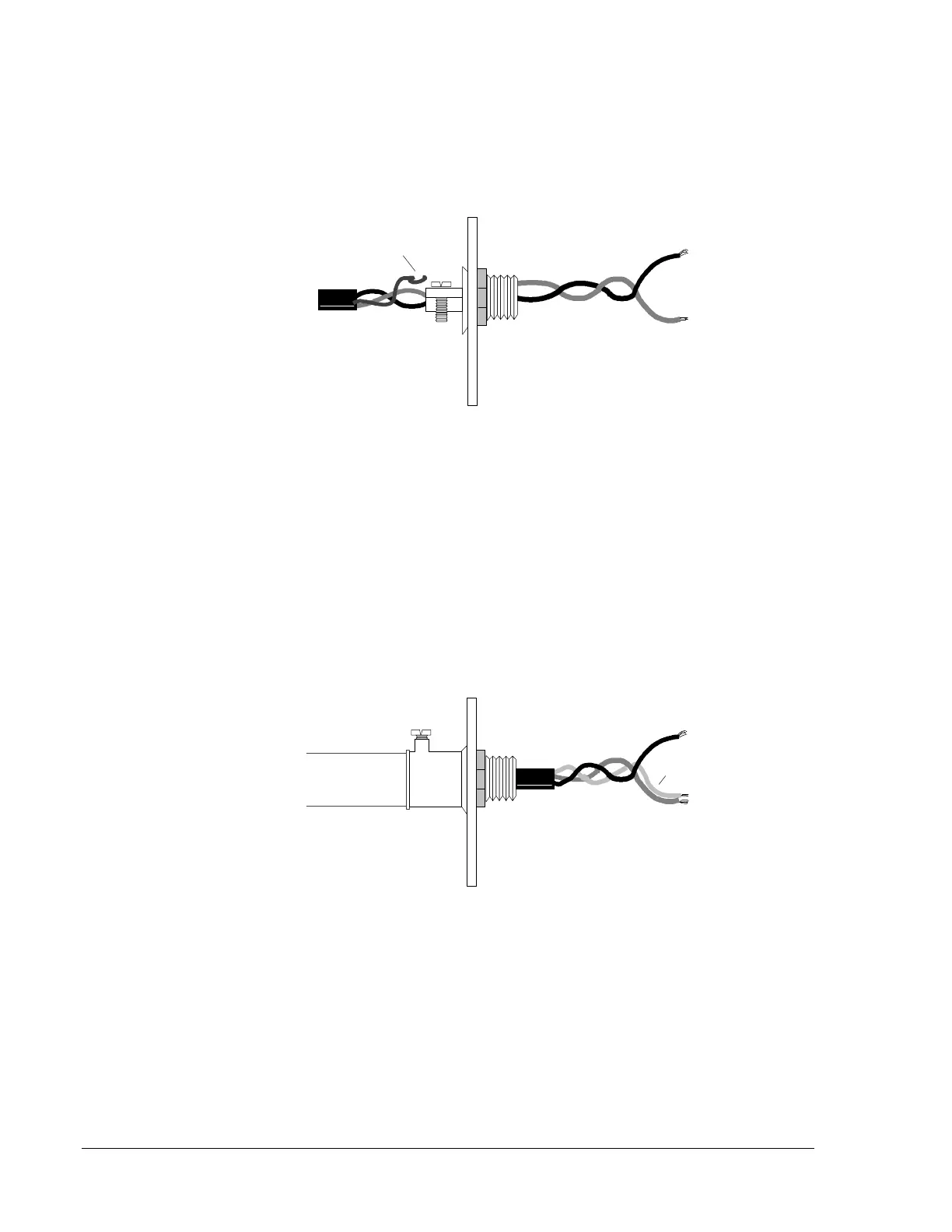
Do not allow the shield drain wire to enter the control panel cabinet.
Connect the drain wire to the outside of the cabinet via a BX-type
connector.
Figure 14: Shield Termination in No Conduit
Shield Termination in Full Conduit
The shield drain wire must be connected to the negative (-) side of the
loop. Do not allow the shield drain wire or the shield foil to touch the
control panel cabinet.
Note: For redundant or isolated redundant field wiring of the
communications loop, connect each end of the shield to the
negative side of the respective channel.
Figure 15: Shield Termination in Full Conduit
Shield Termination in Partial Conduit
Do not allow the shield drain wire to enter the control panel cabinet or the
conduit. Connect the drain wire to the termination point of the conduit run
(such as a single-gang box as illustrated in Figure 16). The conduit cannot
be longer than 20 feet.