Addressable Intelligent Module—AIM-200 Addressable Intelligent Module 59
Operating the AIM-200
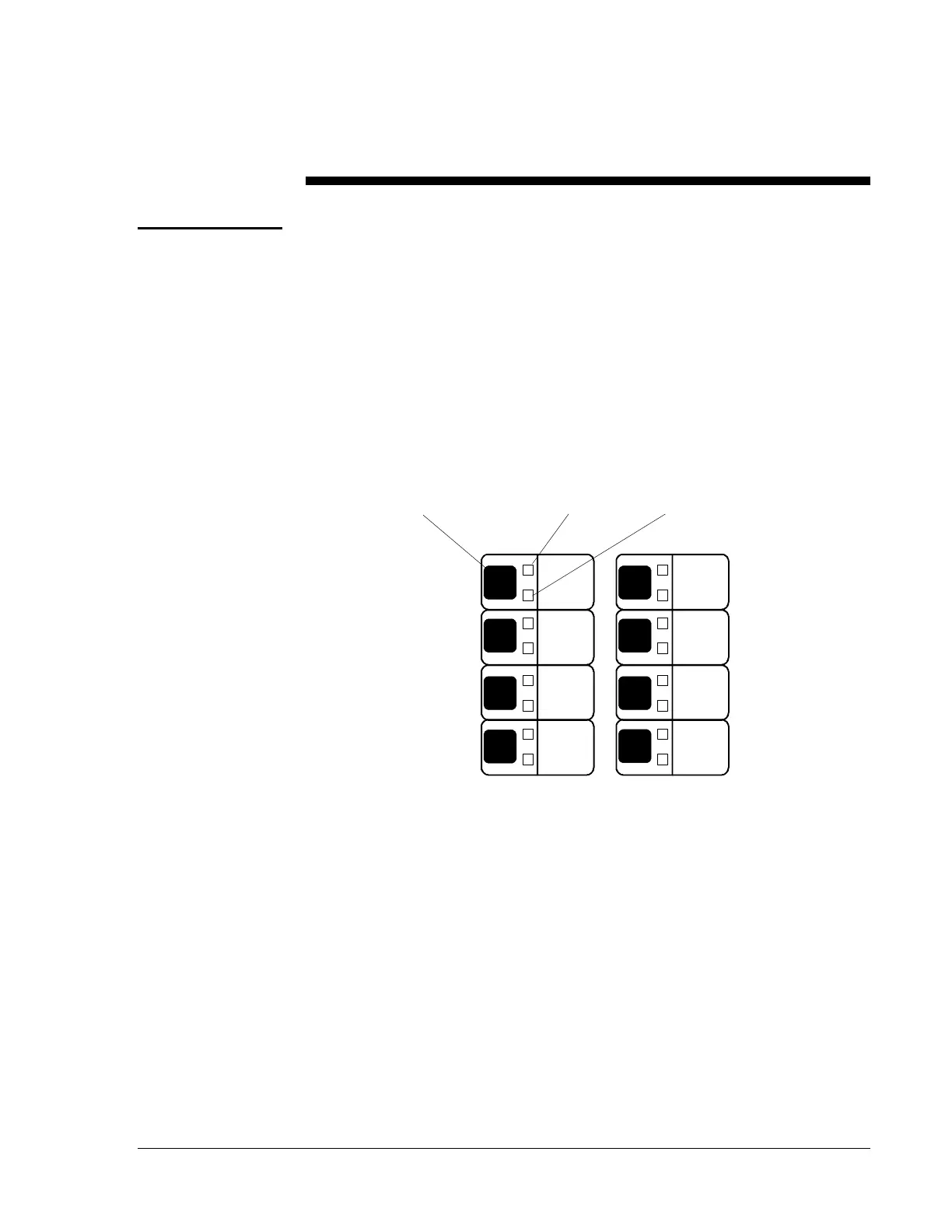
For each of the eight zone displays, a red LED, yellow LED and a switch
are provided. The 198-point capacity of the AIM-200 is assigned to these
zones using a “mapping” technique. Each of the 198 devices may be
mapped to one or more zones. If an initiating device mapped to more than
one zone is alarmed, all mapped zones will be placed into alarm. This type
of zoning could be used to provide a matrix, where one zone indicates the
area and another the type of device. For example, four zones could be
used to indicate floor of alarm, and three zones could be used to indicate
smoke alarm, manual station, and waterflow alarm. The eighth zone could
be used for supervisory devices (the supervisory devices would not be
mapped into a floor zone).
Figure 41: Zone Switch and LED Location
M510CJ Control Modules are activated by the AIM-200 when the zone
that they are mapped to enters an alarm condition. If a M510CJ is mapped
to more than one zone, it will be activated when any of the zones are in
alarm.
The zone LEDs and switches emulate the functions of an IZM-8 module
except when in Program/Display mode. Pressing the switch in
Program/Display mode displays all output circuits in the system that are
mapped to that zone.
Zone Display