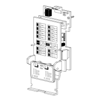
Addressable Intelligent Module—AIM-200 Addressable Intelligent Module 55
Two switches, STEP FORWARD and STEP REVERSE, are provided for
advancing the display. If multiple alarms or troubles exist in the AIM-200,
and the display is automatically advancing through them, pressing either of
these two switches will stop the automatic advance and allow the operator
to control the advancement through the display. If these two switches are
not pressed again during a period of about one minute, the display will
automatically resume stepping through existing events.
Each time a STEP switch is pressed, the digital display advances to the
next higher/lower address that is also in alarm or trouble. After all
addresses in alarm or trouble have been displayed, it returns to the first
address and continues.
NFPA Style 6 field wiring may be used to ensure full operation in the event
of a single break in the loop wiring. When set for Style 6, the AIM-200
latches a wire failure and then must be manually reset to re-test and clear
the fault. When the loop fault is latched on, the AIM-200 turns on the
yellow LOOP FAULT LED and reports trouble for all zones that are not in
alarm. If there is no alarm, “LF” is placed on the digital display. The
RESET switch or the System RESET clears the latch. If a loop fault still
exists, the trouble will then resound and re-latch.
T-tap wiring is not allowed in the Style 6 configuration. Field wiring must
be returned to the AIM-200 terminal block as illustrated in Figure 12.
The green ON-LINE LED will flicker when communications occur on the
interface to the CPU. The SKIP switch is used in programming the
AIM-200. (See the Programming the AIM-200 section of this document.)
This LED and switch are used in programming the AIM-200 (see the
Programming the AIM-200 section of this document).
This LED and switch are used in programming the AIM-200 (see the
Programming the AIM-200 section of this document).
The AIM-200 automatically test all detectors on its SLC loop. This test is
similar to activating a detector with a test magnet.
The module periodically commands each detector, one at a time, to
respond with an appropriate alarm-like signal (pulse on the SLC loop). If
the proper response is not returned, the AIM-200 will register a trouble
condition for that detector. The trouble LED of the zone which that
detector is mapped to will illuminate and the piezo will sound.
Step Switches
Loop Fault LED
and RESET
ON-LINE LED
and SKIP
Switch
ENTER LED and
Switch
Display Status
LED and Switch
Automatic
Detector Test

 Loading...