CK721-A Network Controller Hardware Installation
24-10025-237 Rev. –
3
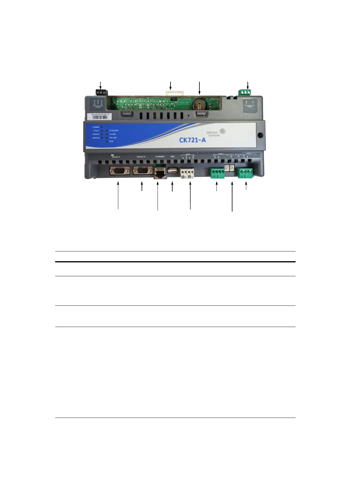
CK721-A CONTROLLER
Table 3: Major CK721-A Components
Component Description
Lithium battery 3V lithium battery used for realtime clock backup.
See Replacing the Lithium Battery on page 4.
Input points Unsupervised binary inputs:
IN1 Indicates AC power loss
IN2 Indicates S300-DIN enclosure tamper state
See Wiring Binary Inputs on page 5.
Output point Form C Relay, SPDT, 24 VDC maximum
The CK721-A provides a relay output for connecting to an external alarm at Binary Out1.
The relay will switch 2A at 24 VDC.
Connectors RS232 A RS-232 Serial Interface, DB9 port for the user interface to a terminal emulator
(workstation or laptop computer). See Connecting CK721-A to a Terminal
Emulator (RS232 Serial Null Modem Cable Wiring) on page 6.
RS232 B KONE serial server elevator or OTIS serial server elevator controller
communications port or ThyssenKrupp serial server communications port to
elevator management system. This port is disabled by default.
RS485A OTIS BMS elevator communication. 9600 bps, even parity, 8 bit per character,
and one stop bit.
RS485B Communication with field devices such as RDR8S, I32O16, RDR2S-A, or
I8O4. 9600 bps, even parity, 8 bit per character, and one stop bit. See Wiring
Between RS485B and the Field Devices on page 5.
RJ45 10/100Base-T network port for host communication. See Connecting CK721-
A to the Network on page 6.
USB Not used
RS232 A
connector
IN1 and IN2
binary inputs
RS485B
connector
Binary output Lithium battery 24VDC power
Ethernet
connector RJ45
DIN clip
RS485A
connector
USB
connector
(not used)
RS232 B
connector
End-of-Line
switches

 Loading...


