Table 2: Termination details
Type of Field
Device
Type of
Input/
Output
Termination Diagrams
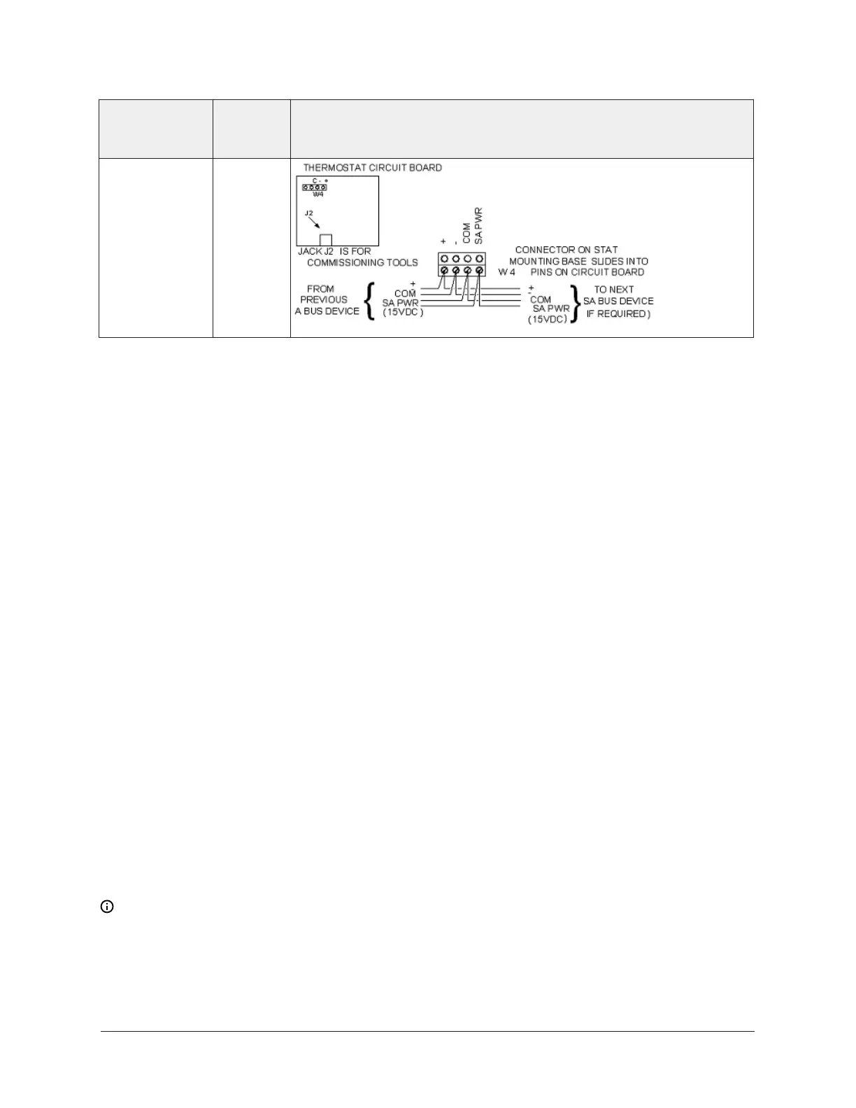
Network Stat
with Terminals
(Fixed Address
= 199)
SA Bus
Terminal wiring guidelines, functions, ratings, and
requirements
This section provides further guidelines on input and output wiring, maximum cable length versus
load current, and SA Bus and supply power wiring.
Input and Output wiring guidelines
Table 3 provides information and guidelines about the functions, ratings, and requirements for
the controller input and output terminals, and Table 3 also references guidelines for determining
proper wire sizes and cable lengths.
In addition to the wiring guidelines in Table 3, observe the following guidelines when wiring CVM
inputs and outputs:
• Run all low-voltage wiring and cables separate from high-voltage wiring.
• All input and output cables, regardless of wire size or number of wires, must consist of twisted,
insulated, and stranded copper wires.
• Shielded cable is not required for input or output cables but is recommended for input and
output cables that are exposed to high electromagnetic or radio frequency noise.
• Cable runs of less than 30 m (100 ft) often do not require an offset in the input/output software
setup.
• Cable runs over 30 m (100 ft) often require an offset in the input/output software setup.
Maximum cable length versus load current
Use the following figure to estimate the maximum cable length relative to the wire size and the
load current (in mA) when wiring inputs and outputs.
Note: The following figure applies to low-voltage (<30 V) inputs and outputs only.
F4-CVM VAV Terminal Equipment Controllers Installation Instructions16