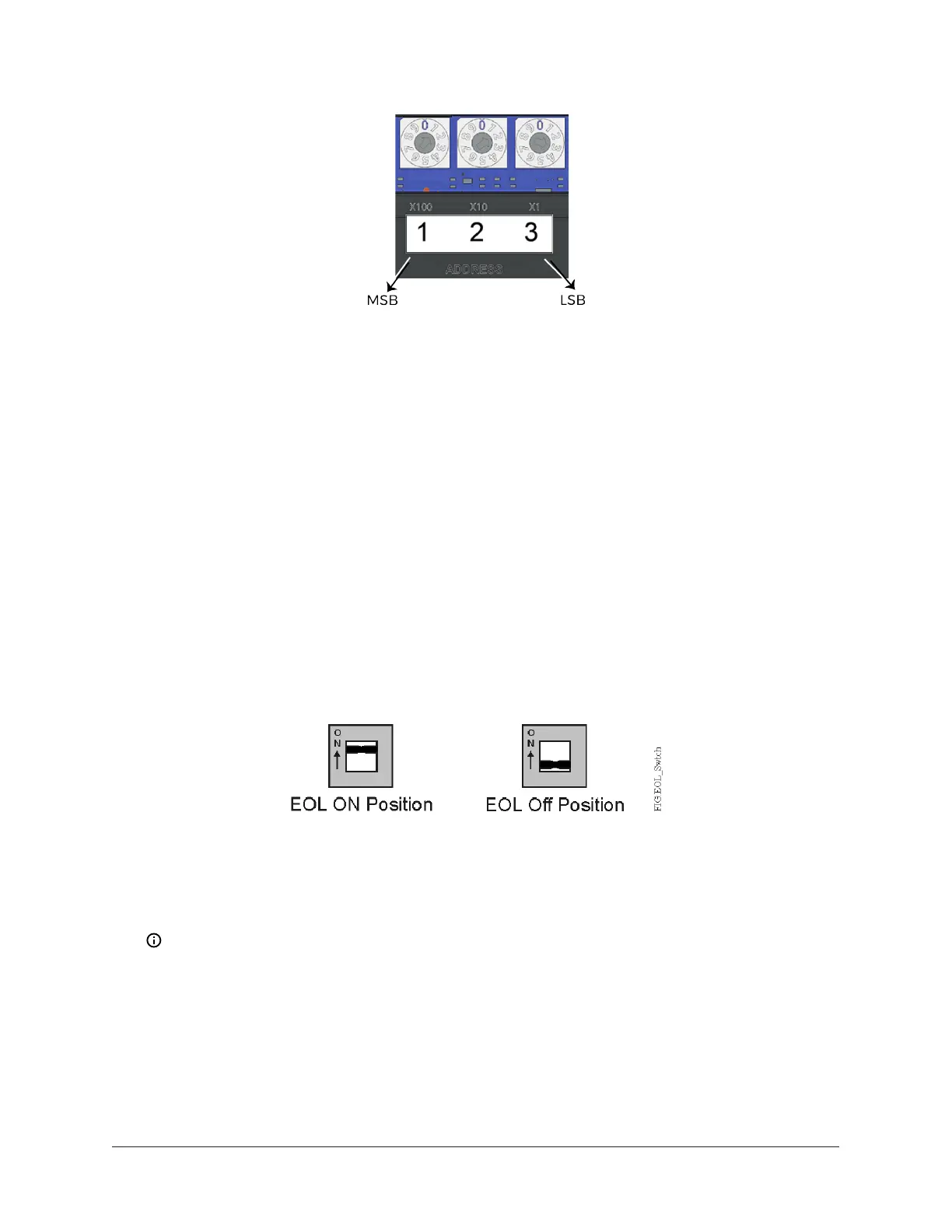
Figure 10: Device address rotary switch block
The device address must match the device address defined in the Controller Configuration Tool
(CCT) under Define Hardware > Network Settings.
To set the device addresses on controllers, complete the following steps:
1. Set a unique and sequential device address for each of the equipment controllers connected
on the FC or SA, starting with device address 4.
2. To ensure the best bus performance, set sequential device addresses with no gaps in the
device address range (4, 5, 6, 7, 8, 9, and so on). The equipment controllers do not need to be
physically connected on the bus in their numerical device address order.
3. Write each controller's device address on the white label below the Device Address Rotary
Switch Block on the controller's cover.
Setting the End-of-Line (EOL) switch
Each CVM controller has an EOL switch, which, when set to ON (up), sets the CVM controller as a
terminating device on the bus. See for the EOL switch location. The default EOL switch position is
OFF (down).End-of-LineSwitch Positions
To set the EOL switch on a CVM controller, complete the following steps:
1. Determine the physical location of the controller on the FC bus.
2. Determine if the controller must be set as a terminating device on the bus.
Note: For detailed information about EOL termination rules and EOL switch settings on
FC buses, refer to the FX-PC Series Controllers MS/TP Communications Bus Technical Bulletin
(LIT-12011670).
3. If the controller is a terminating device on the FC Bus, set the EOL switch to ON. If the
controller is not a terminating device on the bus, set the EOL switch to OFF.
When a controller is connected to power with its EOL switch set to ON, the amber EOL LED on the
controller cover is illuminated.
25F4-CVM VAV Terminal Equipment Controllers Installation Instructions