Network diagram
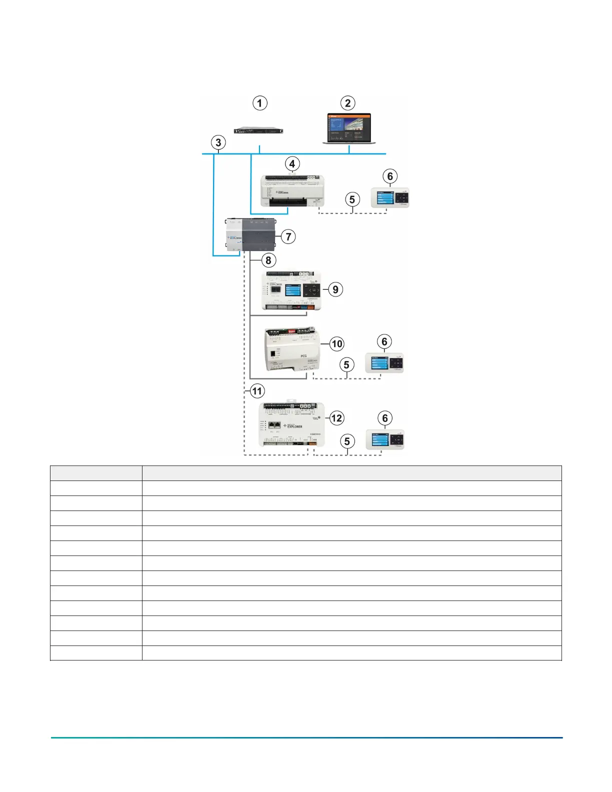
Figure 2: Network diagram example
Callout Description
1 FX Server
2 System User Interface
3 Ethernet/IP network
4 F4-SNC with an F4-DLK0350 Local Controller Display connected
5 SA Bus connection
6 F4-DLK0350 Local Controller Display
7 FX80 Supervisory Controller
8 FC Bus connection
9 F4-CGM with integral display
10 PCG with an F4-DLK0350 Local Controller Display connected
11 BACnet/IP
12 F4-CGE with an F4-DLK0350 Local Controller Display connected
Mounting dimensions
F4-DLK0350 Product Bulletin2