Materials and special tools needed
• Three fasteners appropriate for the mounting surface
(M4 screws or #8 screws)
• One 20 cm (8 in.) or longer piece of 35 mm DIN rail and
appropriate hardware for DIN rail mount (only)
• Small straight-blade screwdriver for securing wires in
the terminal blocks
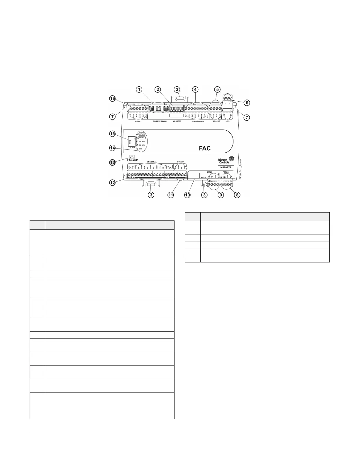
FAC2611 physical features
Figure 1: FAC2611 physical features
Table 1: FAC2611 physical features
Physical feature: description and references
1
Binary Output (BO) Source Power Selection Jumpers:
Position jumpers to select internal or external 24 VAC
supply power for Binary Outputs. (see Binary Output (BO)
source power selection jumpers)
2
Device Address DIP Switch Block. See Setting the device
addresses
3 Mounting Clips (see Mounting)
4
Configurable Outputs (CO) Terminal Block: Can be
defined as Voltage Analog Output (0-10 VDC) or Binary
Output (24 VAC Triac). (see Table 2)
5
Analog Output (AO) Terminal Block: Can be defined as
Voltage Analog Output (0-10 VDC) Current Analog Output
(4-20 mA). (see Table 2)
6
24 VAC, Class 2 Supply Power Terminal Block (see Supply
power terminal block)
7 Cover Lift Tab (see Removing the Controller cover)
8
Field Controller (FC) Bus Terminal Block (see FC bus
terminal block)
9
Sensor Actuator (SA) Bus Terminal Block (see SA bus
terminal block)
10
Sensor Port: (SA Bus) RJ-12 6-Pin Modular Jack (see SA Bus
port)
11
Binary Input (BI) Terminal Block: Dry Contact Maintained
or Pulse Counter/Accumulator Mode (see Table 2)
12
Universal Inputs (UI) Terminal Block: Can be defined as
Voltage Analog Input (0-10 VDC), Current Analog Input
(4-20 mA), Resistive Analog Inputs (0-600k ohm), or Dry
Contact Binary Input. (see Table 2)
Table 1: FAC2611 physical features
Physical feature: description and references
13
End-of-Line (EOL) Switch, located under the cover. (see
Setting the End-of-Line (EOL) switch)
14 LED Status Indicators (see Table 8)
15 FC Bus Port (RJ-12 6-pin Modular Jack) (see FC bus port)
16
Binary Outputs (BO) Terminal Block: 24 VAC Triac (see
Table 2)
Mounting
Observe these guidelines when mounting a field
controller:
• Ensure the mounting surface can support the
controller, DIN rail, and any user-supplied enclosure.
• Mount the controller horizontally on 35 mm DIN rail
whenever possible.
• Mount the controller in the proper mounting position
(Figure 2).
• Mount the controller on a hard, even surface whenever
possible in wall-mount applications.
• Use shims or washers to mount the controller securely
and evenly on the mounting surface.
• Mount the controller in an area free of corrosive vapors
and observe the Ambient Conditions requirements in
Table 10.
• Provide for sufficient space around the controller for
cable and wire connections for easy cover removal
and good ventilation through the controller (50 mm
[2 in.] minimum on the top, bottom, and front of the
controller).
FAC2611 Advanced Application Field Equipment Controller Installation Guide2