Table 6: Termination details
Type of field device
Type of Input/
Output
Termination diagrams
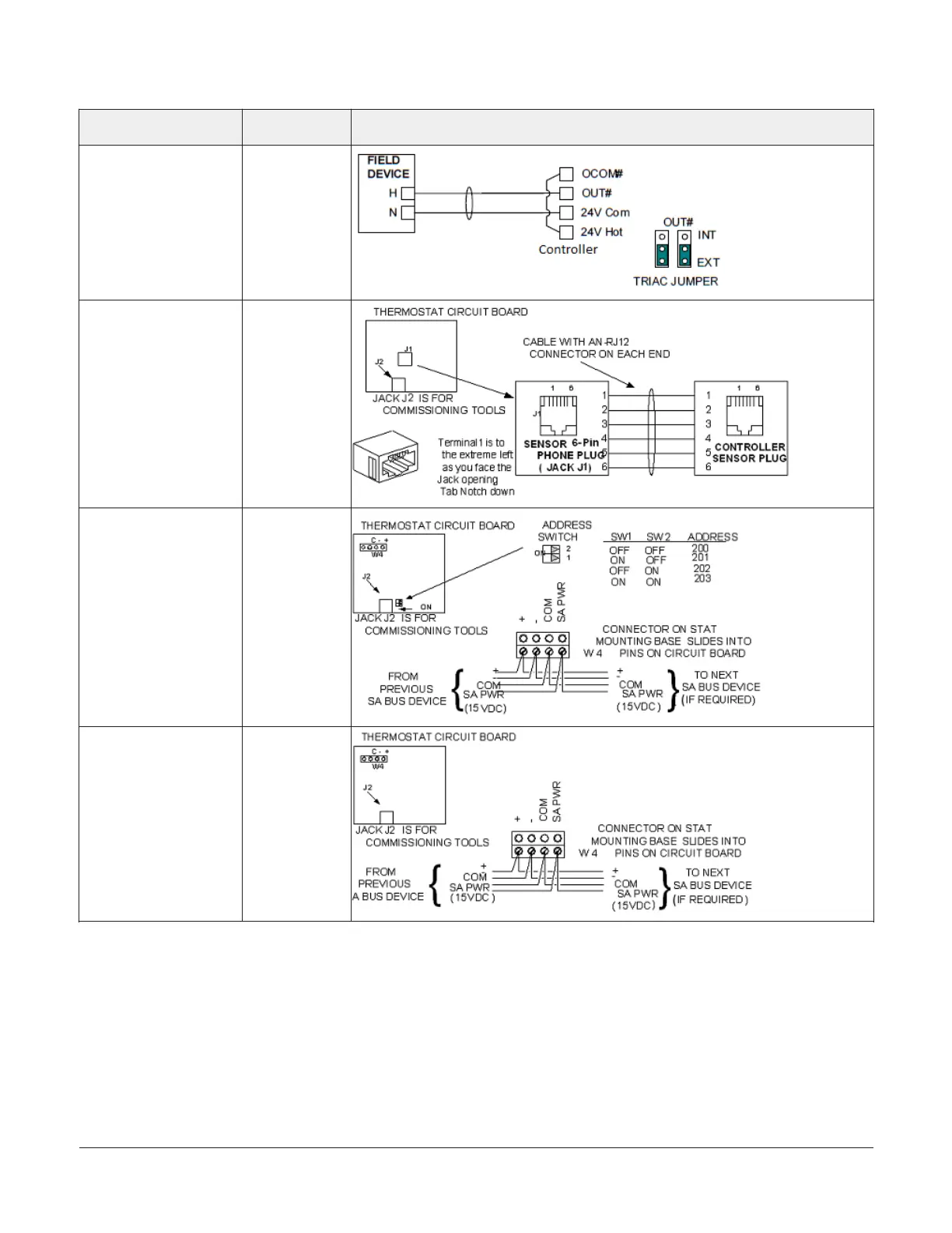
24 VAC Binary Output
(Switch High, Externally
Sourced)
BO
Network Stat with Phone
Jack (Fixed Address = 199)
SA Bus
Network Stat with
Terminals Addressable
SA Bus
Network Stat with
Terminals (Fixed Address
= 199)
SA Bus
Setup and Adjustments
Setting the device addresses
The controllers are master devices on MS/TP (SA or
FC) buses. Before operating the controllers on a bus,
you must set a valid and unique device address for
each controller on the bus. You set a controller's device
address by setting the positions of the switches on the
DIP switch block at the top of the controller () . Device
addresses 4 through 127 are the valid addresses for these
controllers.
The DIP switch block has eight switches numbered
128, 64, 32, 16, 8, 4, 2, and 1. Switches 64 through 1 are
device address switches. Switch 128 is a mode switch that
enables a controller to operate on a ZFR/ZFR Pro Series
Wireless Field Bus. Switch 128 must be set to off for all
hard-wired SA and FC bus applications. Set switch 128 to
ON for wireless FC bus applications only.
FEC26 Field Equipment Controllers Installation Guide16

 Loading...


