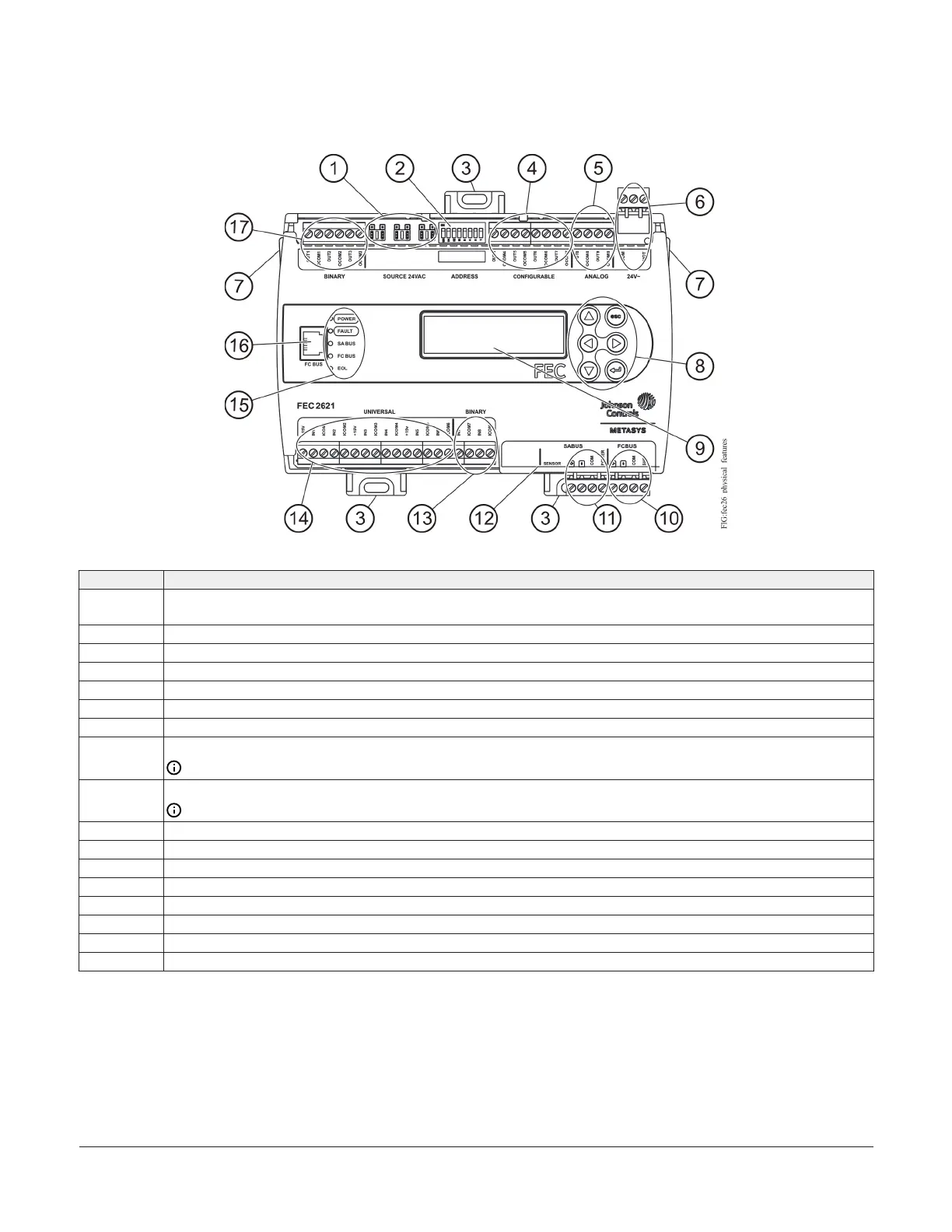
Physical features
Figure 1: FEC2621 physical features
Table 1: FEC2621 Physical Features
Callout Physical Feature: Description and References
1
Binary Output (BO) Source Power Selection Jumper Pin Blocks, 3 – BO Jumper Pin Blocks. See Table 3 for more
information.
2 Device Address DIP Switch Block. See Setting the device addresses for more information.
3 Mounting Clip. See Mounting for more information.
4 Configurable Output (COs) Terminal Blocks. See Table 3 for more information.
5 Analog Outputs (AOs) Terminal Block. See Table 3 for more information.
6 24 VAC, Class 2 Supply Power Terminal Block. See Table 5 for more information.
7 Cover Lift Tab (One of Two). See Removing the controller cover for more information.
8
Display Navigation Buttons. See Setting up an integral or local display.
Note: Not available on all FEC models.
9
Liquid Crystal Display (LCD) Display Area
Note: Not available on all FEC models.
10 Field Controller (FC) Bus Terminal Block. (See FC bus terminal block.)
11 Sensor Actuator (SA) Bus Terminal Block. (See SA bus terminal block.)
12 Sensor Actuator (SA) Bus (RJ-12 6-pin Modular Jack). See SA Bus port.
13 Binary Input (BI) Terminal Block, 2 – Binary Inputs. See Table 3 for more information.
14 Universal Input (UI) Terminal Blocks, 6 – Universal Inputs. See Table 3 for more information.
15 LED Status Indicators. See Table 9 for more information.
16 Field Controller (FC) Bus Port (RJ-12 6-pin Modular Jack). See FC bus port for more information.
17 Binary Output (BO) Terminal Blocks. See Table 3.
Mounting
Observe these guidelines when mounting a controller:
• Ensure the mounting surface can support the
controller, DIN rail, and any user-supplied enclosure.
• Mount the controller horizontally on 35 mm DIN rail
whenever possible.
• Mount the controller in the proper mounting position.
• Mount the controller on a hard, even surface whenever
possible in wall-mount applications.
• Use shims or washers to mount the controller securely
and evenly on the mounting surface.
• Mount the controller in an area free of corrosive vapors
and observe the Ambient Conditions requirements.
FEC26 Field Equipment Controllers Installation Guide 3

 Loading...


