Important: Connect 24 VAC supply power to the
controller and all other network devices so
that transformer phasing is uniform across
the network devices. Powering network
devices with uniform 24 VAC supply power
phasing reduces noise, interference, and
ground loop problems. The field controller
does not require an earth ground
connection.
Wireless Network Applications
The controller can also be installed in a wireless
application using a ZFR/ZFR Pro Wireless Field Bus
Router.
Important: Wireless operation is not approved for
smoke control applications. Refer to the
Metasys System UL 864 UUKL Tenth
Edition Smoke Control System Technical
Bulletin (LIT-12012487) for detailed
requirements and procedures for installing,
commissioning, and operating UL 864
UUKL/UUKLC Listed Metasys system
devices.
To configure a controller for use with the ZFR/ZFR Pro
Series Wireless Field Bus system:
1. Wire the input/output terminals and SA bus.
Note: In wireless network applications, do not
connect any wires to the FC bus terminal
block. (Connect the SA/FC terminal block on
an IOM to an SA bus only.)
2. Connect the ZFR/ZFR Pro Wireless Field Bus Router
to the FC bus port (RJ-12 modular jack) on the front
of the controller.
3. Ensure that the controller's device address DIP
switches are set to the correct device address. See
Setting the Device Addresses.
4. Set DIP switch 128 to ON, which enables wireless
operation on the field controller.
For more information on the ZFR Pro Wireless Field
Bus system, refer to the WNC1800/ZFR182x Pro
Series Wireless Field Bus System Product Bulletin
(LIT-12012320).
For more information on the ZFR 1800 Wireless Field
Bus system, refer to the ZFR1800 Series Wireless
Field Bus System Product Bulletin (LIT-12011336).
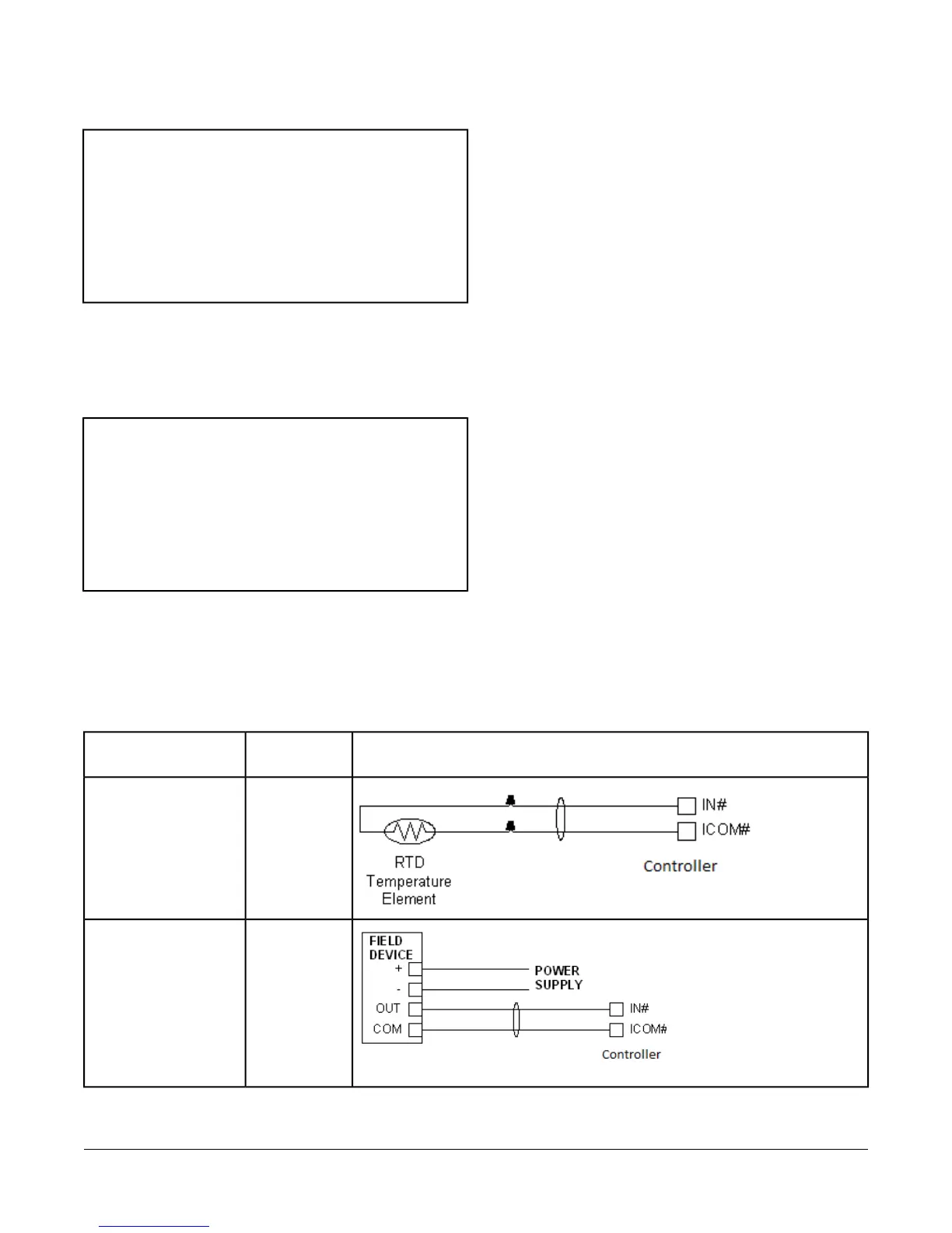
Termination Details
A set of Johnson Controls® termination diagrams provides details for wiring inputs and outputs to the controllers.
See the figures in this section for the applicable termination diagrams.
Table 2: Termination Details
Termination DiagramsType of
Input/Output
Type of Field Device
UITemperature Sensor
UIVoltage Input - External
Source
7FEC26 Field Equipment Controllers Installation Instructions