Removing the Controller Cover
Important: Electrostatic discharge can damage
controller components. Use proper
electrostatic discharge precautions during
installation, setup, and servicing to avoid
damaging the controller.
Important: Disconnect all power sources to the
controller before removing cover and
changing the position of any jumper or the
EOL switch on the controller. Failure to
disconnect power before changing a jumper
or EOL switch position can result in damage
to the controller and void any warranties.
The controller cover is held in place by four plastic latches
that extend from the base and snap into slots on the
inside of the housing cover.
To remove the controller cover:
1. Place your fingernails under the two cover lift tabs on
the sides of the housing cover and gently pry the top
of the cover away from the base to release the cover
from the two upper latches.
2. Pivot the top of the cover further to release it from the
lower two latches.
3. Replace the cover by placing it squarely over the
base, and then gently and evenly push the cover on
to the latches until they snap into the latched position.
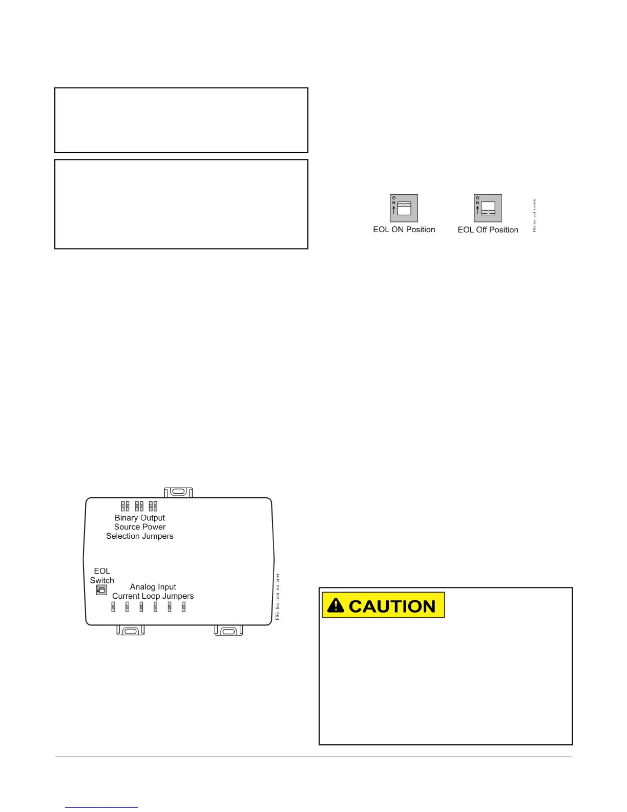
Figure 10: FEC26 with Cover Removed Showing EOL
Switch and Jumper Positions
Setting the End-of-Line (EOL) Switch
Each controller has an EOL switch, which, when set to
ON, sets the controller as a terminating device on the
bus. See Figure 10 for the EOL switch location. The
default EOL switch position is OFF.
Figure 11: End-of-Line Switch Positions
To set the EOL switch on a field controller:
1. Determine the physical location of the controller on
the FC bus.
2. Determine if the controller must be set as a
terminating device on the bus.
Note: Refer to the MS/TP Communications Bus
Technical Bulletin (LIT-12011034)for detailed
information regarding EOL termination rules
and EOL switch settings on FC buses.
3. If the controller is a terminating device on the FC bus,
set the EOL switch to ON. If the controller is not a
terminating device on the bus, set the EOL switch to
OFF.
When a field controller is connected to power with its
EOL switch set to ON, the amber EOL LED on the
controller cover is lit.
Setting the Input and Output
Jumpers
Binary Output (BO) Source Power
Selection Jumpers
Risk of Electric Shock: Disconnect supply power to
the field controller before attempting to adjust the Binary
Output Source Power Selection Jumpers. Failure to
disconnect the supply power may result in electric shock.
Mise En Garde: Risque de décharge électrique:
Débrancher l'alimentation de l'controller avant tout
réglage du Binary Output Source Power Selection
Jumpers. Le non-respect de cette précaution risque de
provoquer une décharge électrique.
22FEC26 Field Equipment Controllers Installation Instructions