FIRECLASS Fire detection system Check the FC-FI Connections
Installation Guide Doc. version 2.0 24
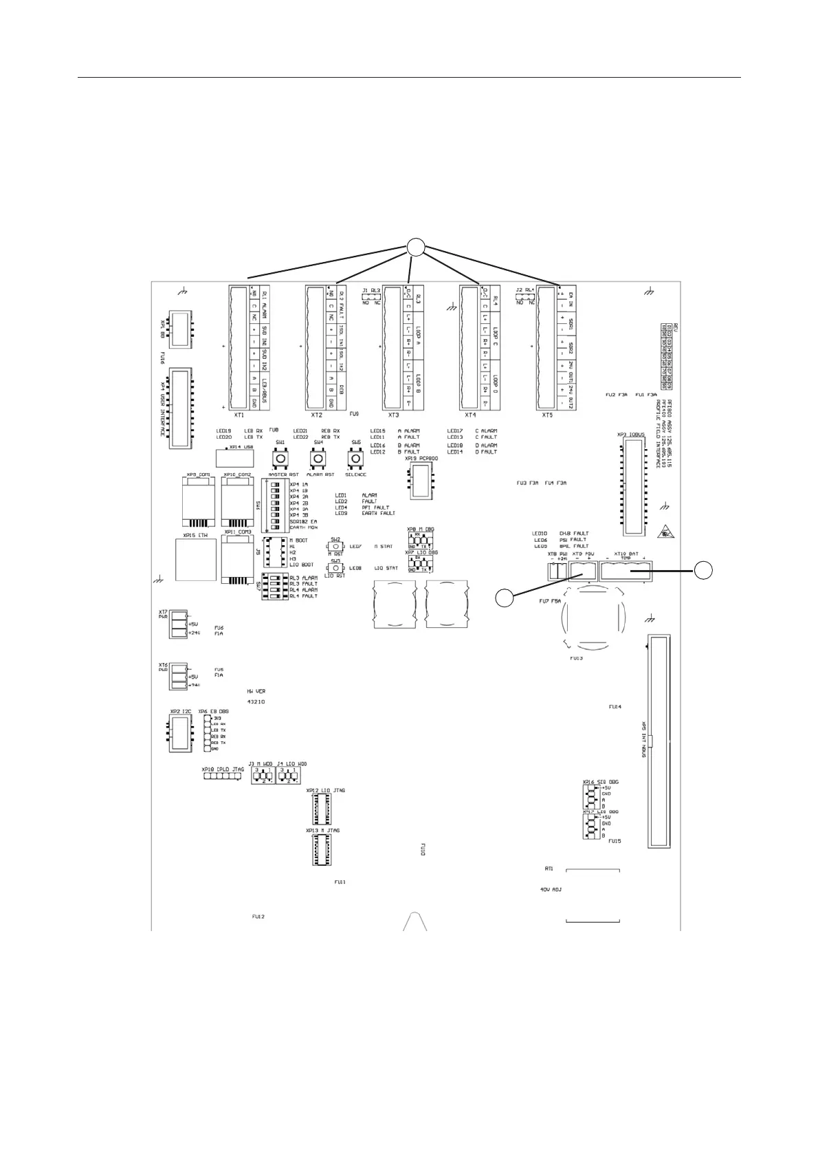
10.4 Check the FC-FI Connections
The FC-FI connections are shown in Fig. 20. Not all of
these are covered in this guide. For the numbered items
‘2’ and ‘3’, these should have been connected in earlier
steps, (which cross-references to this figure).
Fig. 20: FC-FI Connections
1 – Loops, supervised input 1, supervised input 2, sounder, alarm and fault relay, 24V, emergency alarm (EA).
2 – DC cable (black, twin conductor). Marked ‘XT9 PSU’ on the PCB.
3 – To the batteries. Marked ‘XT10 BAT’ on the PCB. See Section “Install the Batteries - FC700 series” on page 14.
1
2
3
2
3
 Loading...