FIRECLASS Fire detection system Mounting the IOB800 and FB800 boards
Installation Guide Doc. version 2.0 37
14.3.1 IOB800 Input Output Expansion Card
Details
Installing the IOB800 is covered in Section “Changing a
Fuse on the PNI800”. Below are more details about the
IOB800 card.
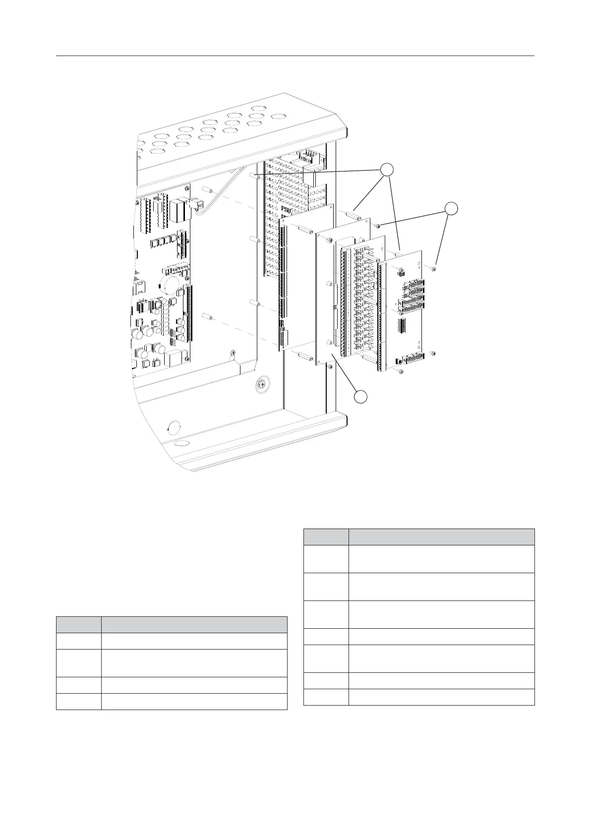
Fig. 28: Mounting Boards on a FC702S Panel
1 – Pillars
2 – Screws
3 – Adapter plate
1
2
3
Item Function
S1 See Table 34
S2 This is a DIP switch. “IOB800 S2 DIP
switch settings”.
XP1 IO-BUS Input connector.
XP2 IO-BUS Output connector.
Table 34: IOB800 - Switch, terminal and connector functions
XP3 Open Collector outputs 1 to 8, inputs 1 to 8
and power +5V connector.
XP4,
XP6
MX-BUS Input connector (not applicable).
XP5,
XP7
MX-BUS Output connector (not applicable)
XT1 Isolated Inputs 1 to 5 connector.
XT2 Isolated Inputs 6 to 8 and power 24V con-
nector
XT3 Relay Output 1 to 4 connector
XT4 Relay Output 5 to 8 connector
Item Function
Table 34: IOB800 - Switch, terminal and connector functions
 Loading...