070.550-IOM (JUN 2016)
Page 11
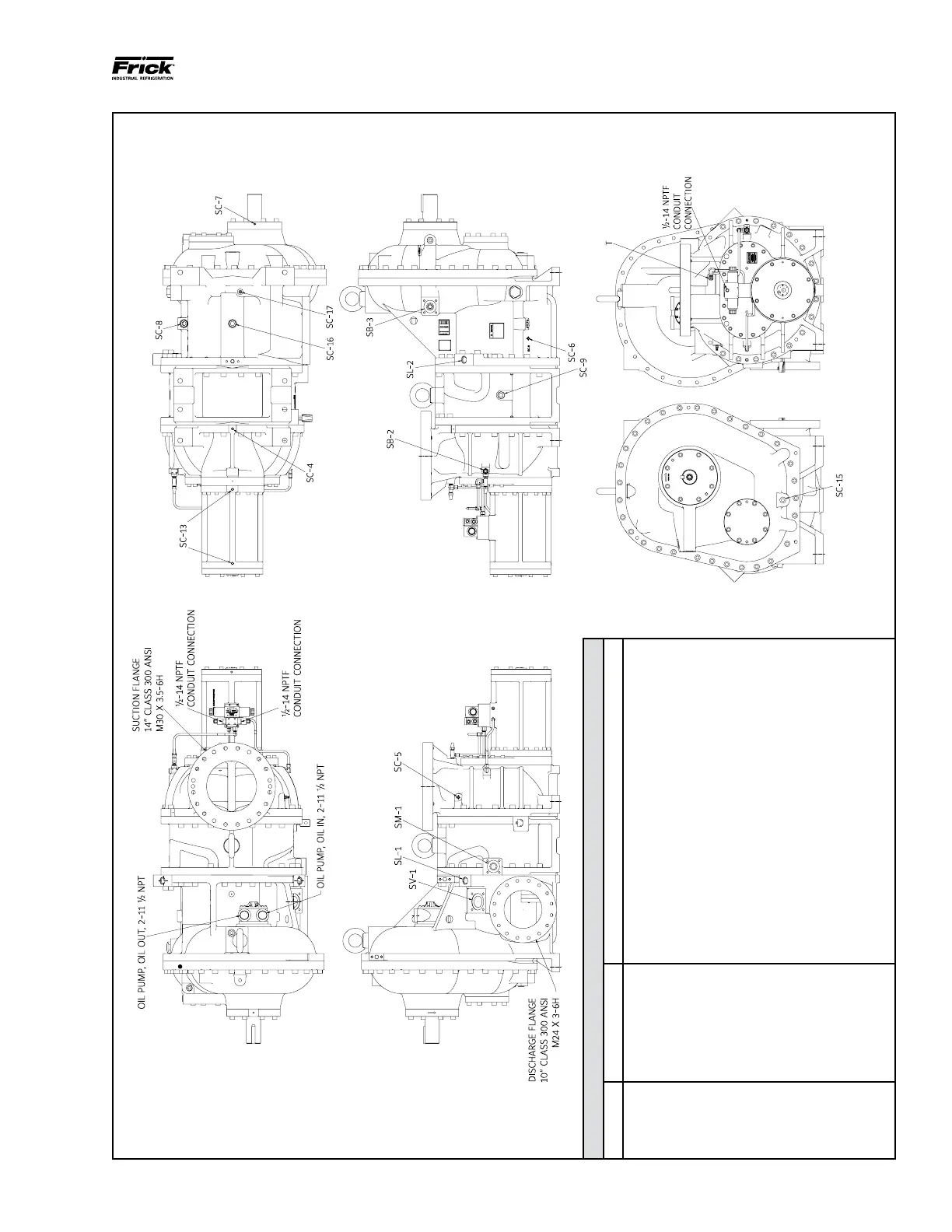
NGC GAS ROTARY SCREW COMPRESSOR
INSTALLATION
Figure 6. Port Locations, NGC 400/450.
NOTE: Model 400 is shown for illustrative purposes only. Congurations of other compressors will vary.
NGC 400/450
SYMBOL PORT SIZE DESCRIPTION
SB-2 3/4-14 NPTF
Inlet Bearings, Balance Pistons, Manifold Block Pressure
SB-3 2" Square Flange Compressor Oil Supply
SC-4 1/2-14 NPTF Inlet Oil Drain
SC-5 3/8-18 NPTF Inlet Pressure
SC-6 3/8-18 NPTF Discharge Pressure
SC-7 1/8-27 NPTF Seal Weepage
SC-8 1 1/4-11 1/2 NPT Closed Thread Drain
SC-9 1 1/2-11 1/2 NPT Closed Thread Drain
SC-13 1/2-14 NPTF Cylinder Oil Drain
SC-15 1 1/4-11 1/2 NPTF Gear Cover Oil Drain
SC-16 1 1/2-11 1/2 NPT
Discharge Housing Oil Drain
SC-17 1/2-14 NPTF
Discharge Housing Sump Drain
SL-1 1 1/4-11 1/2 NPT Low Vi Liquid Injection
SL-2 1 1/4-11 1/2 NPT High Vi Liquid Injection
SM-1 2" Square Flange Main Oil Injection
SV-1 3" Square Flange Economizer
T 1/2-14 NPTF Manifold Block Tank

 Loading...


