070.550-IOM (JUN 2016)
Page 19
NGC GAS ROTARY SCREW COMPRESSOR
INSTALLATION - OPERATION - MAINTENANCE
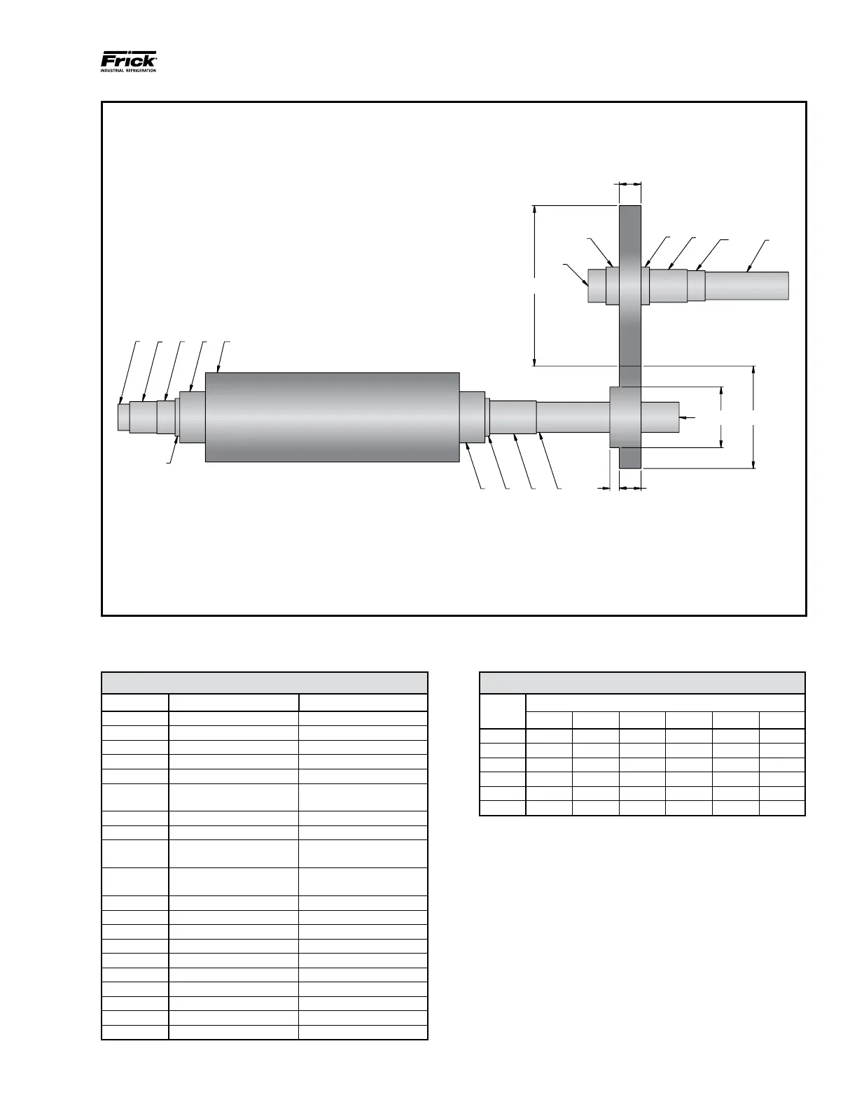
Figure 14. Torsional Analysis, NGC and NGCH 400/450 Driveline and Gear Dimensions.
NGC/NGCH Driveline Dimensions (Less Gears)
SEGMENT DIAMETER* LENGTH*
1 3.5 1.54
2 4.13 3.61
3 4.33 2.39
4 5 .62
5 6.75 3.38
6 11.79
15.37 (NGC/H 400)
33.53 (NGC/H 450)
7 6.75 3.38
8 5 .62
9 4.33
4.96 (NGC 400/450)
6.16 (NGCH 400/450)
10 4
10.98 (NGC 400/450)
9.79 (NGCH 400/450)
11 See Gear Dimensions See Gear Dimensions
12 See Gear Dimensions See Gear Dimensions
13 4.33 2.36
14 5 5
15 See Gear Dimensions See Gear Dimensions
16 5 1.12
17 4.33 5
18 4 2.35
19 3.75 11
20 4 4.93
*Dimensions in inches
NGC/NGCH Gear Dimensions
GEAR
SET
SEGMENT*
11 11A 12 12A 15 15A
A 8.13 1.25 16.13 3 21.1 2.75
B 8.13 1.25 14.6 3 22.63 2.75
C 8.13 1.25 12.76 3 24.48 2.75
D 8.13 1.25 11.43 3 25.8 2.75
E 8.13 1.25 10.48 3 26.75 2.75
F 8.13 1.25 9.66 3 27.57 2.75
*Dimensions in inches
NOTE: 1. All segments are labeled on the driveline.
Refer to corresponding tables for dimensions.
2. Male rotor body diameter, Segment 6, is an equivalent
diameter which is dependent on rotor prole geometry.
3. Diagram is subject to change. This drawing is current
as of 04/16/2014 (Rev. 09). Article 3800 in the CES
manual displays current revision level.
4. This is a representation of an NGC and NGCH 400/450
driveline and intended to be used for torsional
vibration analysis.
1
32
4
5
6
8 9 10
11
13
14
16
17
18
19
Male Rotor
Jackshaft
20
12
11A 12A
15
15A
7
TORSIONAL ANALYSIS