070.550-IOM (JUN 2016)
Page 14
NGC GAS ROTARY SCREW COMPRESSOR
INSTALLATION
Figure 8 - Alignment between Compressor and Engine
WARNING
Make sure all coupling components are properly at-
tached before starting the engine. It is critical to pre-
vent them from ying off and possibly causing serious
injury or death.
CAUTION
Injury could occur if loose clothing, etc, becomes en-
tangled on the spinning engine shaft, coupling compo-
nents or the compressor shaft. Always install all guards
and covers before starting engine.
COMPRESSOR/MOTOR COUPLINGS INSTALLATION
Before installing the coupling perform the following:
1. Inspect the shaft of the compressor to ensure that no
nicks, grease, or foreign matter is present.
2. Inspect the coupling components to make sure that they
are free of burrs and are clean.
3. Checkthatthekey(issoequipped)tsthecompressor
hub and shaft properly.
4. During installation of the coupling hub be carefully not
to put any excess load on the compressor bearings and
shaft seal in any way. Never hammer on the hub as this
can lead to bearing failure.
5. Coupling shall be aligned according to coupling manu-
facturer’s requirements.
6. Check that no axial force will be transmitted to the
compressor.
7. Check and redo the alignment after 200 hours of
operation. See the maintenance schedule.
ELECTRICAL INSTALLATION
SLIDE STOP TRANSMITTER
The slide stop transmitter measures the position of the
slide stop (SS) using a 4 to 20mA signal that is sent to your
control system. The controller will adjust the position of
SS according to system pressures. The correct SS position
is important to achieve the most efcient compressor
operation. Connect to +/- and signal. Refer to Johnson
Controls- Frick compressor panel instructions S90-010 for
calibration procedure.
Figure 9 - Slide Stop Transmitter
CAPACITY SLIDE VALVE TRANSMITTER
The slide valve transmitter measures the position of the
slide valve (SV) and sends a 4 to 20mA signal to your
control system. The controller will adjust the position of
the SV according to the engine load set point. The correct
position is important to properly load the compressor and
engine. It is important not to overload the compressor and
engine. Observe the maximum power input and ensure
design limitations are not exceeded. Connect to +/- and
signal. Refer to Johnson Controls- Frick compressor panel
instructions for calibration procedure S90-010.
ENDVIEW
DIN CONNECTOR
STAINLESS STEEL WELL
HEAT ISOLATOR
CAST ALUMINUM HOUSING
COMPRESSOR UNLOAD CYLINDER
SHADED AREA SHOWS
CAPACITY LINEAR TRANSMITTER
Figure 10 - Capacity Slide Valve Transmitter
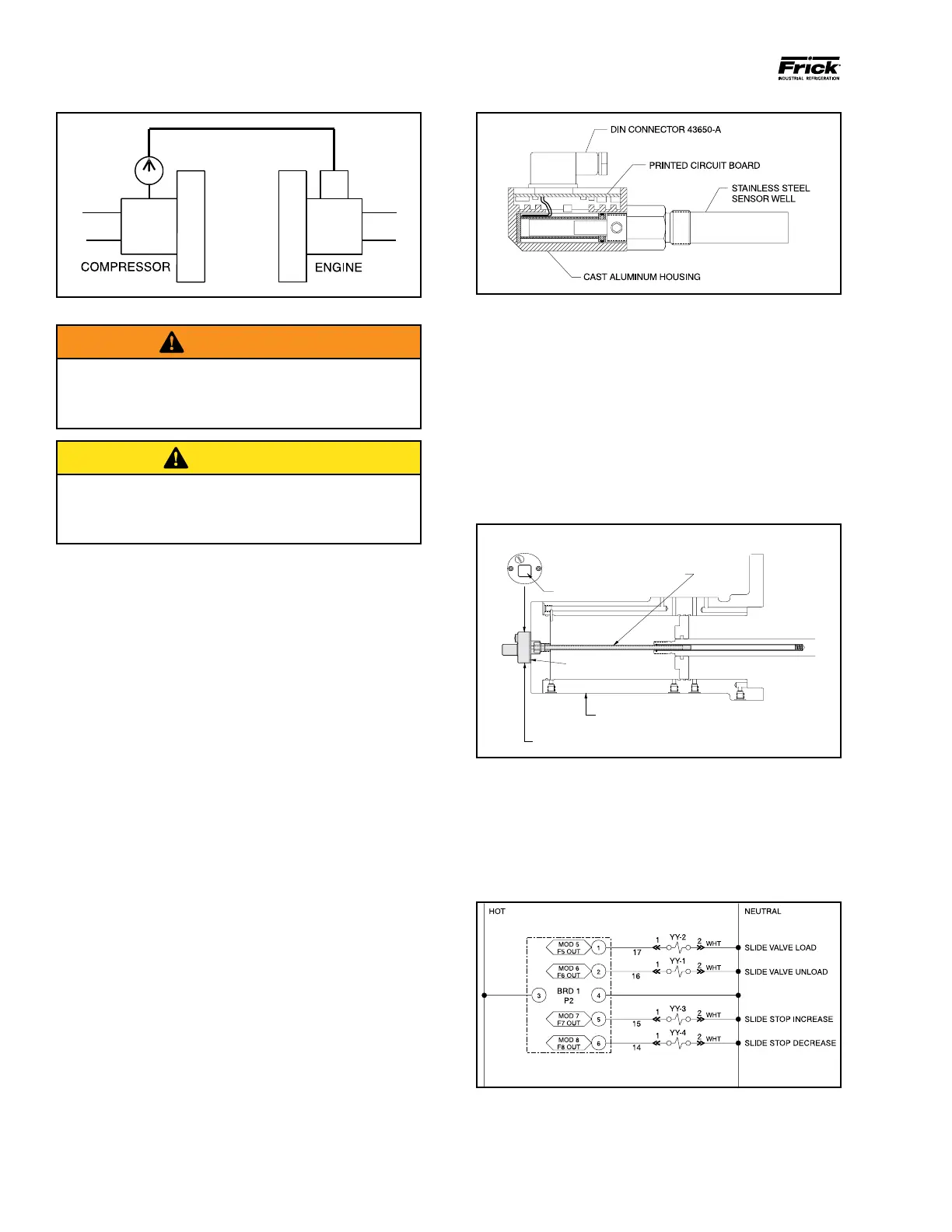
DIRECTIONAL CONTROL VALVES
Solenoids YY1, YY2, YY3 and YY4 must be wired to give
the correct function. A description of their function is given
in the OPERATION chapter. For control system information
refer to Johnson Controls - Frick Compressor Control Panel
S90-010. See wiring diagram in Figure 7.
Figure 11 - Directional Control Valve Wiring Diagram