070.550-IOM (JUN 2016)
Page 6
NGC GAS ROTARY SCREW COMPRESSOR
INSTALLATION - OPERATION - MAINTENANCE
CONSTRUCTION DETAILS
HOUSING: All NGC screw compressor castings are close
grain, pressure tight, grey cast iron to ensure structural
integrity and mechanical and thermal stability under all
operating conditions.
ROTORS: The rotors are machined from AISI-1141 steel to
the exacting tolerances of the latest industry standard
asymmetric prole. The four-lobed male rotor is directly
connected to the driver. The six-lobed female rotor is
driven by the male on a thin oil lm.
BEARINGS: Antifriction bearings with an adjusted L
10
rated
life in excess of 50,000 hours, at design conditions are used
for reduced frictional horsepower and superior rotor
positioning, resulting in reduced power consumption,
particularly at higher pressure ratios. Cylindrical roller
bearings are provided to handle the radial loads and the
thrust loads are absorbed by four-point contact bearings. In
addition, thrust balance pistons are provided to reduce the
thrust load and improve bearing life.
GEARS: Helical Gears are made of AISI 8620H steel per
ASTM A534. Design life for the gears is 50,000 hr. at
maximum load conditions. Gears can be changed as needed
by the customer to keep engines operating at full load as
wellhead pressure drops.
SHAFT SEAL: The compressor shaft seal is a single-face
type with a spring-loaded carbon stationary surface riding
against a cast iron rotating seat. The seal is capable of
controlling leakage up to 400 psig, but is vented to low
pressure to provide extended life.
VOLUMIZER VARIABLE VOLUME RATIO CONTROL: The
Johnson Controls - Frick compressor includes a patented
method of varying the internal volume ratio to match the
system pressure ratio. Control of the internal volume ratio
eliminates the power penalty associated with over-
compression or under-compression. Volume ratio control is
achieved by the use of a slide stop which is a movable
portion of the rotor housing that moves axially with the
rotors to control discharge port location. The slide stop is
moved by hydraulic actuation of a control piston. The range
of adjustment is listed in the table below.
STEPLESS CAPACITY CONTROL: Capacity control is
achieved by use of a movable slide valve. The slide valve
moves axially under the rotors to provide fully modulated
capacity control from 100% to minimum load capacity.
Minimum load capacity varies slightly with compressor
model, pressure ratio, discharge pressure level, and rotor
speed. See the table below for minimum capacity for all
NGC models.
The slide valve is positioned by hydraulic movement of its
control piston. When in the unloaded position, gas is
bypassed back to suction through a recirculation slot before
compression begins and any work is expended, providing
the most efcient unloading method available for part-load
operation of a screw compressor.
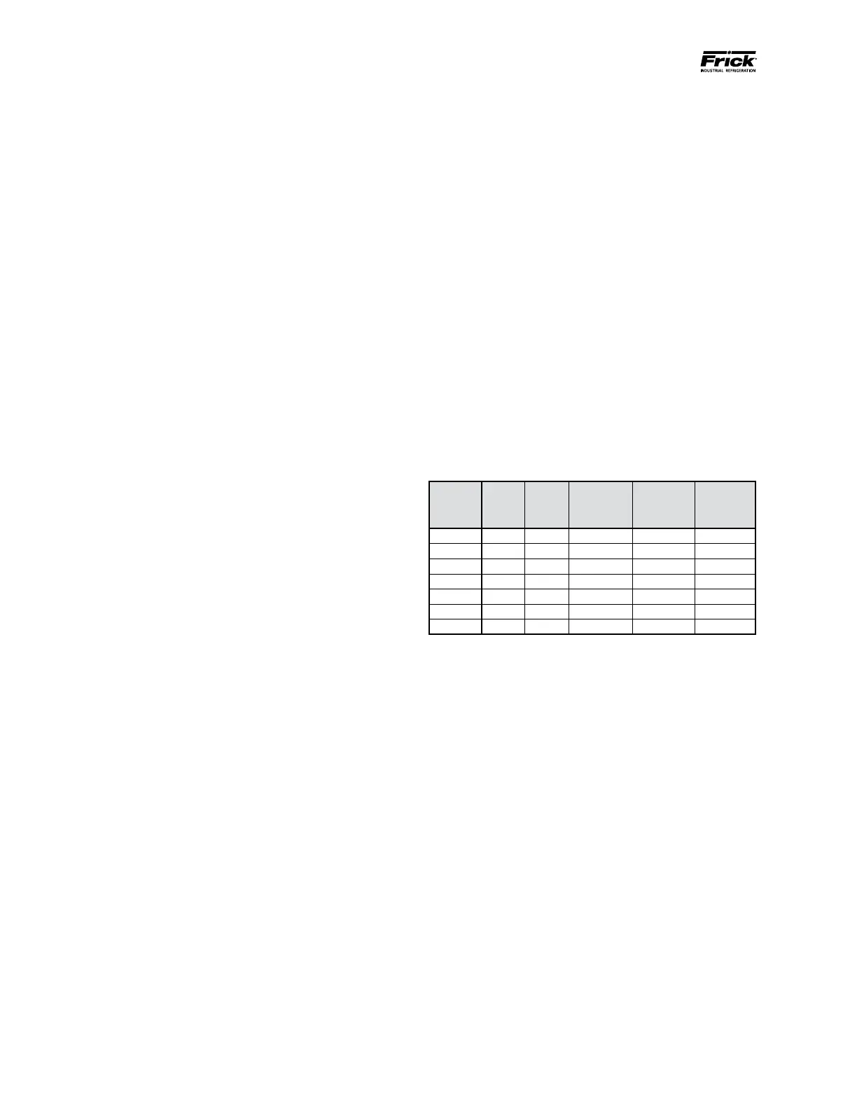
TABLE 1. COMPRESSOR VOLUME & CAPACITY RATIO
NGC
MODEL
MIN.
VI
MAX.
VI
MIN.
CAPACITY
SLIDE
VALVE
TRAVEL*
SLIDE
STOP
TRAVEL*
100 2.2 5.0 12 %
6.50 2.53
150 2.2 5.0 12 % 8.18 3.19
200 2.2 5.0 15 % 7.84 3.06
250 2.2 5.0 23 % 9.89 4.75
300 2.0 4.1 20 % 16.94 6.95
400 2.2 5.0 12 % 8.99 3.69
450 2.4 4.5 26 %
15.48 6.40
* Dimensions in inches

 Loading...


