070.550-IOM (JUN 2016)
Page 16
NGC GAS ROTARY SCREW COMPRESSOR
OPERATION
High stage compressor loading: The compressor loads
when MSV solenoid YY2 is energized and oil ows from the
unload side of the cylinder out port SC1, through valve
ports A and T to compressor suction. Simultaneously,
discharge pressure loads the slide valve.
High stage compressor unloading: The compressor unloads
when MSV solenoid YY1 is energized and oil ows from the
oil manifold through valve ports P and A to cylinder port
SC1 and enters the unload side of the cylinder.
Simultaneously, gas on the load side of the cylinder is
vented through port SC2 and valve BP to compressor
suction.
NOTICE
To control the rate of loading and unloading, throttle
the needle valve at SC1 port.
DOUBLE-ACTING MODE - Booster (low differential)
Open valve at SC1
Open valve at SC2
Close valve at BP (bypass)
Booster Compressor Loading: The compressor loads when
MSV solenoid YY2 is energized and oil ows from the oil
manifold through valve ports P and B to cylinder port SC2
and enters the load side of the cylinder. Simultaneously, oil
contained in the unload side of the cylinder ows out cylinder
port SC1 through valve ports A and T to compressor suction.
Booster Compressor Unloading: The compressor unloads
when MSV solenoid YY1 is energized and oil ows from the
oil manifold through valve ports P and A to cylinder port
SC1 and enters the unload side of the cylinder.
Simultaneously, oil contained in the load side of the cylinder
ows out of compressor port SC2 through valve ports B and
T to compressor suction.
NOTICE
To control the rate of loading and unloading, throttle
valves SC1 and SC2.
NOTICE
To slow all valve movements - loading, unloading, and
VI change - throttle valve 2.
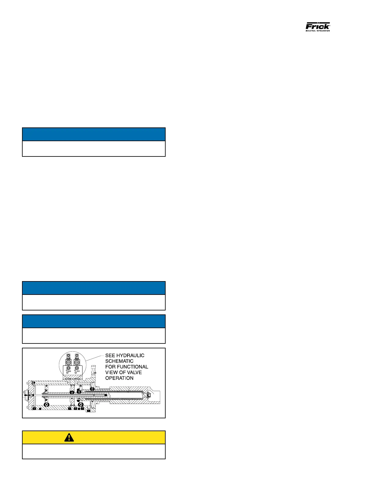
Figure 13 - Solenoid Valve Block
CAUTION
NEVER open valve BP and valve SC2 at the same time
during compressor operation.
VOLUMIZER VOLUME RATIO CONTROL
Open valve at SC3
Open valve at SC4
Compressor VI increase: The volume ratio Vi is increased
when MSS solenoid valve YY3 is energized and oil ows
from the oil manifold through valve ports P and A to
compressor port SC3, enters the increase side of the
cylinder and overcomes the decrease spring tension.
Simultaneously, oil ows from SC4 port through valve ports
B and T to compressor suction.
Compressor VI decrease: The volume ration Vi is decreased
when MSS solenoid valve YY4 is energized and oil ows
from the oil manifold through valve ports P and B to
compressor port SC4, enters the decrease side of the
cylinder. Simultaneously, oil ows form SC3 port through
valve ports A and T to compressor suction.
TO CONTROL THE RATE OF VI CHANGE, THROTTLE THE
NEEDLE VALVE AT SC3 PORT.
LOW AMBIENT OPERATION
It is recommended that package oil separators be insulated
as a minimum requirement to preserve the heat generated
by the oil heaters, to prevent condensation and secure
lubrication at start-up.
INITIAL STARTUP
Prior to the start-up, the packager’s prestart check must
be accomplished.
INITIAL STARTUP PROCEDURE
Having performed the packager’s prestart check, the
compressor unit is ready for start-up. It is important that an
adequate gas load be available to load test the unit at
normal operating conditions. The following points should
be kept in mind during initial start-up.
1. For proper and safe operation, the compressor must be
run at the proper speed and discharge pressure. Exceeding
design conditions creates a potential hazard.
2. After 1 to 3 hours of operation adjust oil cooling system.
3. Pull and clean suction strainer after 24 hours of operation.
If it is excessively dirty, repeat every 24 hours until system
is clean. Otherwise, follow the normal maintenance
schedule.
4. Perform vibration analysis if equipment is available.
NORMAL STARTUP PROCEDURE
1. Conrm system conditions permit starting the
compressor.
2. Start.
3. Observe the compressor unit for mechanical tightness of
the external piping, bolts and valves. Ensure that the
machine has no oil and vapor leaks. If any of these occur,
shut down the compressor and correct the problem as
necessary using good safety precautions.

 Loading...


