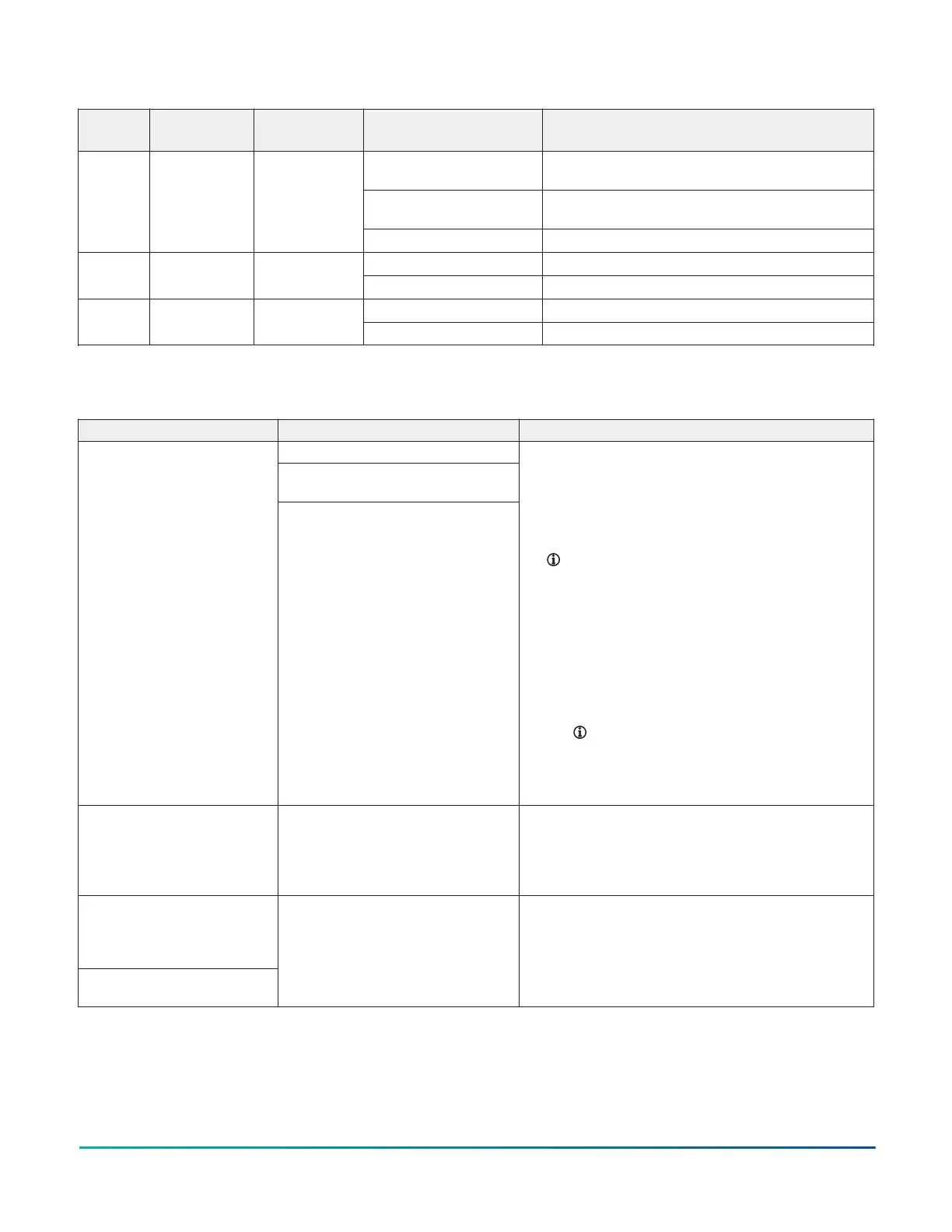
Table 3: FW LED states
LED
label
LED color Normal state State Description
Constant rapid blinks Communication error between the FM-06
module and the base board
On steady Firmware upgrade in process. Ensure no power
loss occurs during this period.
ERR Red Off steady
Off steady No errors
1 Hz blinks Normal operationSTS Green 1 Hz blinks
Off steady Controller fault
1 Hz to 5 Hz blinks Normal data communicationTXRX Yellow 1 Hz to 5 Hz
blinks
Off steady No data transmission
Troubleshooting
Table 4: FW troubleshooting
Problem Cause Solution
The transformer shorted.
The 24 VAC powered sensor is not wired
with the same polarity as the controller.
The controller does not turn
on due to one of the following
problems:
• The transformer trips. Power
is at the transformer primary
and there is no voltage at
the secondary.
• The breaker or fuse trips.
Power is at transformer
primary. You find 24 V
at secondary and 0 V at
breaker or fuse.
The RS-485 bus device is not wired with
the same polarity as the controller.
1. Ensure that the polarity of ~24 V COM, +15 V COM, and
SA BUS COM on the controller, auxiliary devices, and
input and output devices is the same.
2. Verify that the short circuit is resolved with an ohm-
meter.
3. Reset the breaker or fuse, or replace the transformer.
Note: If you replace the transformer, replace
it with a model that uses a resettable circuit
breaker. A circuit breaker makes it easier to solve
wiring problems.
4. To verify the connection, complete the following steps:
a. Disconnect the secondary of the 24 VAC
transformer.
b. Use an ohm-meter to measure between ~24 V H
and G at the controller. Ensure that no short circuit
occurs.
Note: If your installation requires that you
earth ground the transformer secondary,
verify that the earth ground connection
is valid and not shared between multiple
pieces of equipment.
Analog output mode is invalid. 0
V to 10 V output is set to 100%,
but output terminals are less
than 10 V.
Load impedance is lower than 2K ohms. 1. Ensure that the voltage control device load impedance
is higher than 2,000 ohms. For more information, refer
to voltage device manufacturer specification.
2. Disconnect the connected device and verify that the
value you require is present.
Analog mode for a configurable
output is invalid. For example,
0 V to 10 V output results in an
unwanted offset of up to 1 V.
The Common Reference is
incorrect.
The COM terminal is not connected. 1. Connect the COM terminal of the configurable output
to the common of the connected end device.
2. Measure the output and verify that it matches the
command.
3. Disconnect the connected device and verify the
commanded value is present.
FW-14 Quick Start Guide10