Table 1: FW-14 features
Callout Description
1 DIN rail
2 Enclosure mount
3 Cover screw
4 Hot (H) and ground (G) terminal
5 Digital output (DO) and COM terminals
6 Universal output (UO) and COM terminals
PWR Power LED
ERR Error LED
STS Status LED
TXRX Transmitting or receiving
communication LED
DO1 and DO2 Digital output status LED
RST Reset button. For more
information on resetting the
controller, refer to EasyIO FW
Series User Reference.
7
SVC Service button
8 RP-SMA female antenna jacks
9 RS-485 serial port terminals
10 Antennas
11 Ethernet port
12 Universal input (UI) and COM terminals
13 Mounting clips
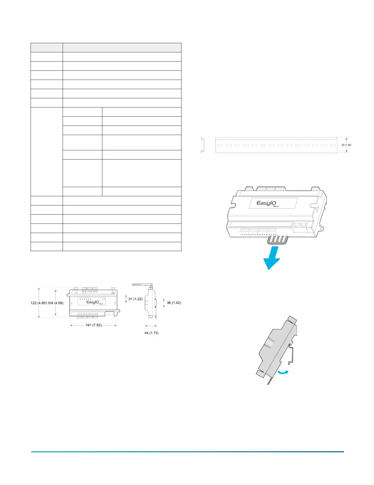
FW-14 dimensions
Figure 3: FW-14 dimensions, in. (mm)
Parts included
• One FW-14 controller with removable terminal blocks
• Two Wi-Fi 2.4 Ghz, 2.2dBi antennas
• One Pack Sheet
Required tools and parts
One small flathead screwdriver to secure wires to terminal
blocks.
Mounting guidelines
The following section lists location considerations, how to
mount the controller on a DIN rail and how to mount the
controller on an enclosure base plate.
Mounting locations to avoid
• Areas with excessive moisture, corrosive fumes, or
explosion vapors
• Locations where excessive vibration or shock occurs
• Locations with excessive electrical noise, such as
large magnetic interference or variable speed drive
modules
Mounting the controller on a 35mm DIN
rail
1. Mount a section of 35 mm (1.38 in.) DIN rail
horizontally on the enclosure base plate.
Figure 4: 35 mm DIN rail
2. Pull the bottom mounting clip outward from the
controller to the extended position.
Figure 5: Pulling the mounting clip outwards
3. Hang the controller on the DIN rail by the hooks at
the top of the DIN rail channel on the back of the
controller and position the controller firmly against
the DIN rail.
Figure 6: Placing the controller on the DIN rail
4. To secure the controller to the DIN rail, push the
mounting clips up.
Figure 7: Closing the mounting clips (rear view)
FW-14 Quick Start Guide2