5. Optional: For added security, use DIN rail end
clips. For the location if the DIN rail end clips, see
Figure 1.
Mounting the controller to an enclosure
base plate
About this task:
If a DIN rail mount is not practical, the controller features
two mounting holes to screw mount the controller to an
enclosure base plate.
1. Place the controller on the enclosure surface and
mark the enclosure mounting holes on the surface.
For more information, see Enclosure mounting
holes in Figure .
2. Drill both holes in the enclosure base plate.
3. Screw the controller to the enclosure base plate.
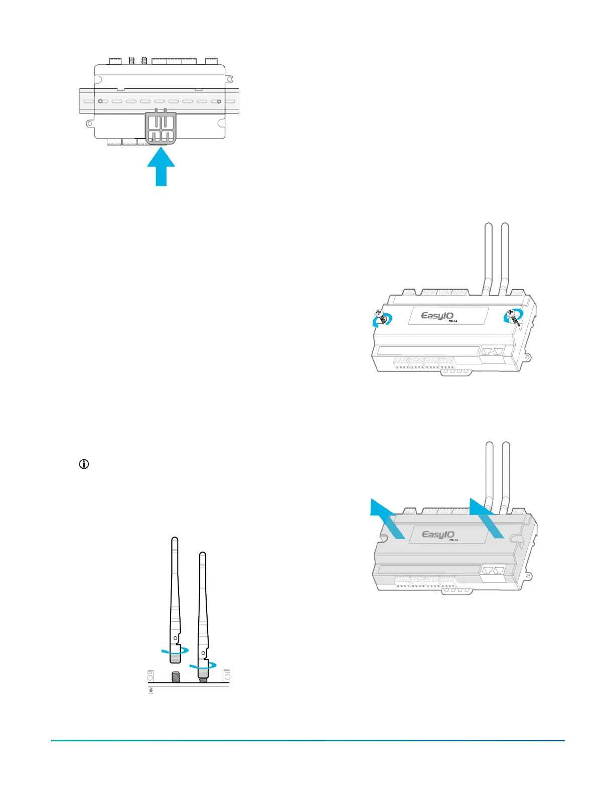
Installing the antennas
1. Locate the two RP-SMA female jacks. See Figure 1.
2. To connect the male antenna connectors to the
female RP-SMA jacks, screw on the antennas in a
clockwise direction.
Note: For a secure connection hold the metal
part of the RP-SMA male connector. A poor
connection reduces reception when you
tighten the antennas to the female RP-SMA
jack.
Figure 8: Screwing on the antennas
3. Adjust the direction of the antennas to find the best
reception. For more information about antenna
reception, refer to Wireless Network (Wi-Fi) in EasyIO
FW Series Network Connectivity.
Removing the controller cover
About this task:
Remove the controller cover to access the circuitry,
jumpers, and to better access the reset and service
buttons.
1. Use a Philips screwdriver to unscrew both of the
top cover screws.
Figure 9: Unscrewing the cover
2. Hold both ends of the top cover and remove it. If
the top cover is stuck, separate the cover with a
standard screwdriver.
Figure 10: Removing the cover
FW-14 Quick Start Guide 3