FX-PCA4911 physical features
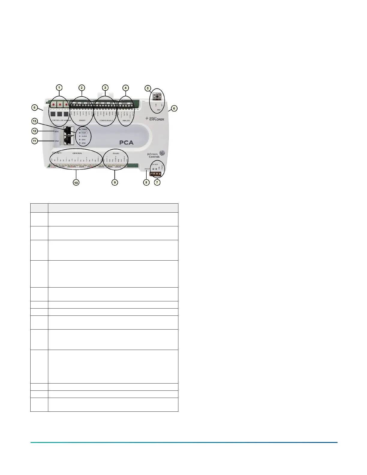
The following figure displays the physical features of
a FX-PCA4911, and the accompanying table provides a
description of the physical features and a reference to
further information where required.
Figure 1: FX-PCA4911 physical features
Table 1: Physical features
Physical feature: description and references
1
Controller Number Rotary Switches: can be numbered
from 000 to 999. See Setting the Controller Number.
2
Binary Outputs (BO) Terminal Block: 24 VAC Triac. See I/
O terminal blocks, ratings, and requirements .
3
Configurable Outputs (CO) Terminal Block: 0–10 VDC
or 24 VAC Triac. See I/O terminal blocks, ratings, and
requirements .
4
Analog Output (AO) Terminal Block: Can be defined as
Voltage Analog Output (0–10 VDC) or Current Analog
Output (4–20 mA). See I/O terminal blocks, ratings, and
requirements .
5
24 VAC, Class 2/SELV Supply Power Terminal Block. See
Supply power terminal block.
6 Cover Lift Tab (One of Two)
7 SA Bus Terminal Block. See SA bus terminal block.
8
Sensor Port: (SA Bus) RJ-12 6-Pin Modular Jack. See SA
bus terminal block.
9
Binary Input (BI) Terminal Block: Dry Contact Maintained
or Pulse Counter/Accumulator Mode. See I/O terminal
blocks, ratings, and requirements .
10
Universal Inputs (UI) Terminal Block: Can be defined
as Voltage Analog Input (0–10 VDC), Current Analog
Input (4–20 mA), Resistive Analog Inputs (0–600kΩ), or
Dry Contact Binary Input. See Input and output wiring
guidelines.
11 ETH2 Ethernet Port for BACnet IP Communications
12 ETH1 Ethernet Port for BACnet IP Communications
13
LED Status Indicators. See Troubleshooting the
Controllers.
FX-PCA4911 Advanced Application Controller Installation Guide2